
Lightning Protection & Surge Prevention for Electric Fencing
Engineering-level guidance on protecting electric fence energizers and systems from lightning strikes, power surges, and voltage transients through proper grounding, surge suppression, and system design
Why Lightning Protection Is Critical for Electric Fencing
Lightning strikes and electrical surges represent the single largest cause of electric fence energizer failure in agricultural and perimeter security applications. Yet lightning protection remains the most frequently omitted component during fence installation, resulting in avoidable equipment loss and operational downtime.
The engineering reality is counterintuitive: you do not need a direct lightning strike to destroy an energizer. Indirect voltage transients induced through fence lines, soil conductivity paths, or utility grid connections can generate sufficient potential difference to overwhelm internal protection circuits and damage sensitive electronics instantly.
Why this happens: Lightning energy follows the path of least resistance to ground. When a strike occurs within several hundred feet of your fence system, the massive ground potential rise creates voltage gradients through soil. If your energizer grounding system and lightning protection grounding system share a common ground plane without proper separation, surge current will flow directly through the energizer, seeking the lowest impedance path to earth. This is not a design flaw in the energizer—it is a predictable consequence of inadequate system design.
What happens if protection is omitted: Internal voltage regulators fail first, followed by capacitor rupture and circuit board carbonization. In AC-powered units, the failure often propagates backward into household wiring. Replacement costs typically exceed $300–800 per incident, not including livestock escape risk during the protection gap.
How Lightning and Surges Damage Electric Fence Systems
Understanding the three primary energy pathways allows you to design protection against each mechanism rather than relying on generic solutions.
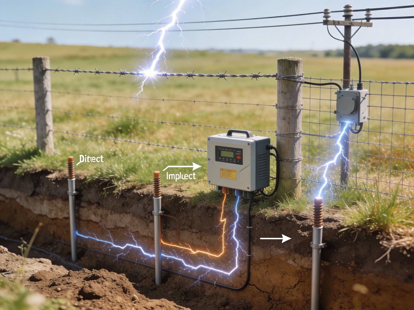
Direct Lightning Strikes to Fence Wire
A direct strike injects 20,000–200,000 amperes into the fence conductor within microseconds. This current seeks ground through all available paths simultaneously—fence posts, energizer terminals, and ground rods. Without a dedicated low-impedance lightning ground, the energizer becomes part of the discharge path.
Failure mechanism: Internal spark gaps and metal oxide varistors are rated for 10–20 kA maximum. Beyond this threshold, internal components vaporize and create carbon tracking across circuit boards, rendering the unit unrepairable.
Engineering reality: No energizer can survive a direct strike without external protection. The goal is to divert 95%+ of surge energy to a dedicated ground system before it reaches the energizer terminals.
Indirect Ground-Induced Voltage Transients
When lightning strikes soil within 300–500 feet of your fence, it creates a radial voltage gradient spreading outward from the strike point. Ground potential rise can exceed 100,000 volts near the strike, decreasing with distance. If your fence crosses this voltage gradient, a potential difference develops between different sections of fence wire.
Why this damages energizers: The fence wire acts as a conductor connecting two points at different potentials. Current flows along the wire seeking equilibrium, entering the energizer if it represents a low-resistance path to local ground. This is identical to connecting a battery across the energizer terminals—it forces current through components designed for voltage output, not current input.
What makes it worse: Long fence runs increase the probability of spanning high voltage gradients. Fences exceeding 1/4 mile should employ multiple lightning arresters along the fence line, not just at the energizer.
Power Grid Surges and Utility-Side Transients
Statistically, this is the most common damage pathway for AC-powered energizers. Utility switching operations, nearby lightning strikes to power lines, and transformer failures generate voltage spikes ranging from 2,000–10,000 volts with sub-millisecond rise times.
Why internal protection fails: Most energizers contain basic metal oxide varistors on the AC input, rated for 6 kV surge immunity. However, these components degrade with each transient event. After 50–100 surge absorptions, their clamping voltage increases and response time slows. The next significant surge exceeds their capacity and destroys internal circuitry.
The distance problem: Utility-side surges do not respect your fence grounding system. They enter through the AC power cord, making energizer ground rod quality irrelevant. External surge protection at the outlet or service panel is the only effective defense.
Key Lightning Protection System Components
Effective lightning protection requires three independent systems working together, each addressing a specific failure pathway:
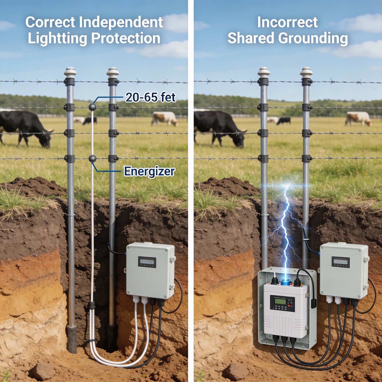
Arresters create a low-impedance path to ground that activates at 3,000–5,000 volts—below energizer damage threshold but above normal operating voltage. Critical requirement: the arrester ground system must be electrically isolated from the energizer ground by 20–65 feet minimum. Shared grounding creates a direct conduction path into the energizer, defeating the protection purpose.
Provides the low-resistance discharge path required for arrester function. Ground resistance below 10 ohms is ideal; 25 ohms is acceptable in dry soil. Multiple 8-foot ground rods driven to depth and interconnected with heavy copper wire create parallel resistance reduction. Why separation matters: During a surge event, the lightning ground system rises to several thousand volts relative to remote earth. If energizer ground connects to this system, the energizer experiences the full voltage rise, damaging internal components despite the arrester’s presence.
These components increase the impedance of the surge path through the energizer while decreasing impedance to the protection ground. A choke coil presents high reactance to fast-rising transients while passing low-frequency fence pulses. Spark gaps provide backup protection if the primary arrester fails or becomes degraded. Together they create preferential current flow toward the protection ground rather than through the energizer.
Lightning Arrester Installation Best Practices
Correct Installation Location and Lead Length
The arrester must be positioned to intercept surge energy before it reaches the energizer fence terminal. Install the arrester within 6–12 inches of the point where the fence lead-out wire connects to the main fence line, slightly on the fence side of the energizer.
Why location is critical: Every foot of wire between the fence and the arrester adds inductance, creating voltage drop during the surge’s rapid rise time. A 6-foot lead wire can develop several thousand volts of inductive voltage drop, allowing that potential to appear across the energizer terminals before the arrester activates. This delay permits damage despite proper arrester function.
Lead Wire Requirements
- Use minimum 10 AWG copper wire for all arrester connections
- Keep fence-side lead under 12 inches; under 6 inches preferred
- Keep ground-side lead under 24 inches with no sharp bends
- Never coil excess wire—cut to proper length
- Avoid right-angle bends; use gradual curves minimum 4-inch radius
What happens with long or coiled leads: Wire inductance is proportional to length and increases dramatically with coiling. A coiled 6-foot lead can present 10–15 microhenries of inductance. During a surge with 10 kA/microsecond rise time, this creates 100,000–150,000 volts of inductive kickback—far exceeding the arrester’s voltage rating and making it ineffective.
Fence-Side vs Grid-Side Protection Strategy
Fence-side arresters address lightning entering from the fence wire. Power-side surge protectors defend against utility grid transients. Both are required for comprehensive protection because surge energy does not originate from a single source.
Common installation error: Installing only fence-side protection while ignoring grid-side exposure. Field data shows 60–70% of energizer failures originate from power line surges, making grid-side protection statistically more important than fence-side protection.
Video: Proper Lightning Arrester Installation Technique
This installation demonstration emphasizes the critical importance of short lead wire lengths and independent grounding paths. The video illustrates how shared grounding between the arrester and energizer systems creates a conductive loop that redirects surge energy into the energizer rather than safely to earth. Key takeaway: separation distance between grounding systems determines whether protection functions as designed or fails catastrophically during surge events.
Independent Grounding System Requirements
This is the single most misunderstood aspect of electric fence lightning protection and the most common installation error. The lightning protection grounding system must be electrically and physically separate from the energizer’s operational grounding system. Connecting these two systems together—either intentionally or through inadequate separation—creates a direct conduction path for surge energy into the energizer.
Why Grounding Separation Is Mandatory
The voltage rise problem: When a lightning arrester diverts surge current to its ground system, those ground rods do not remain at zero volts. The ground resistance (typically 10–25 ohms) multiplied by surge current (10,000–50,000 amperes) creates a ground potential rise of 100,000–1,250,000 volts at the arrester ground rods.
This voltage decreases rapidly with distance from the ground rods due to soil resistance. At 20 feet separation, the voltage has dropped to 10–20% of the peak. At 65 feet, it approaches near-zero relative to remote earth.
What happens with shared grounding: If the energizer ground rods connect to the lightning ground rods, the energizer ground rises to the same multi-thousand-volt potential as the lightning ground. Since the energizer case and internal circuits reference this ground, and the fence terminal connects through the arrester to this same ground, no voltage difference exists to drive the surge away from the energizer. Instead, the surge distributes through all connected paths—including through the energizer’s internal circuitry.
The result: The arrester still functions, but it diverts surge energy into the energizer rather than away from it. This is worse than having no arrester because it creates a false sense of protection while ensuring damage.
| Ground System | Purpose | Minimum Separation | Target Resistance |
|---|---|---|---|
| Energizer Ground | Normal fence circuit completion | — | Below 300 ohms |
| Lightning Protection Ground | Surge energy dissipation to earth | 20–65 feet from energizer ground | Below 25 ohms (below 10 ohms ideal) |
Soil Conditions and Ground Rod Requirements
Ground resistance varies by orders of magnitude depending on soil type and moisture content:
- Clay or loam with high moisture: 10–50 ohms per 8-foot rod
- Sandy soil or gravel: 100–300 ohms per rod
- Dry or rocky soil: 500+ ohms per rod
What this means: In poor soil conditions, you cannot achieve adequate grounding with 2–3 rods. Six to ten rods may be required, driven in a straight line with 10-foot spacing and interconnected with continuous copper wire. Parallel resistance combination reduces total system resistance: three 90-ohm rods yield 30 ohms combined; six rods yield 15 ohms.
Testing requirement: Proper installation includes ground resistance measurement using a 3-pole or clamp-on resistance tester. Without measurement, you cannot verify adequate protection. Target resistance below 25 ohms; below 10 ohms preferred.
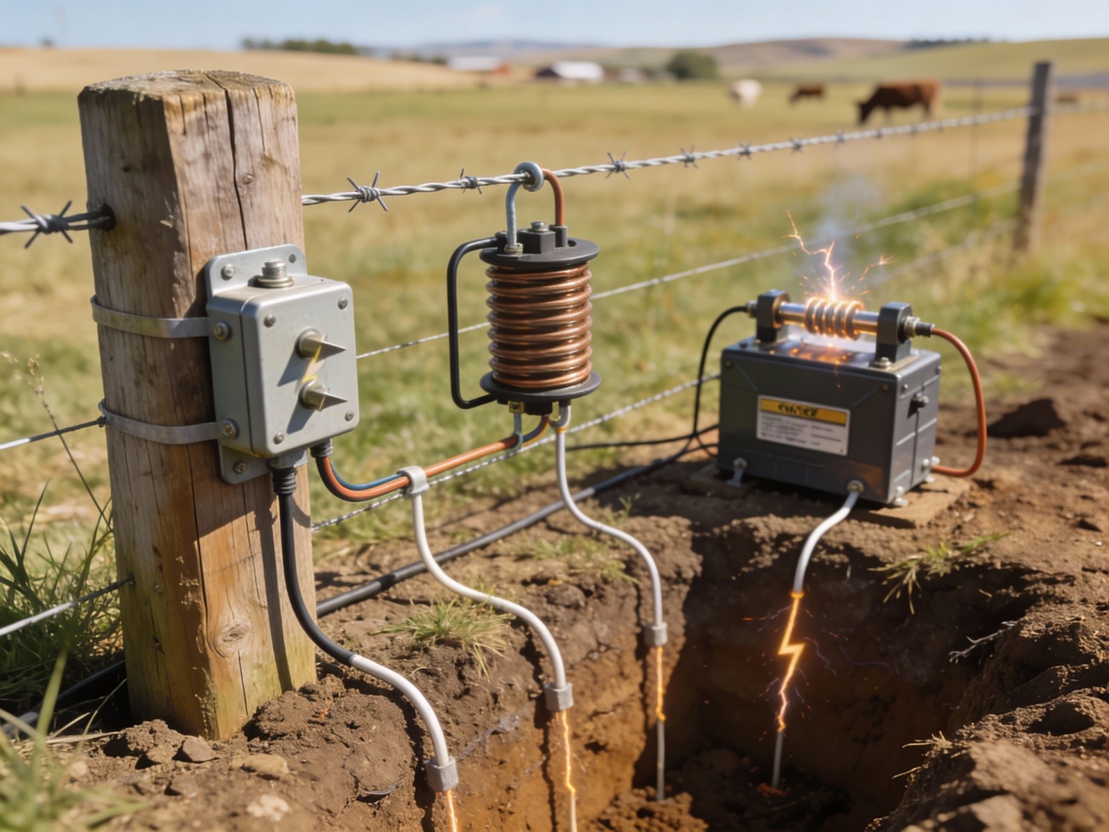
Choke Coils and Spark Gaps Explained
These components provide secondary protection layers and increase the impedance differential between the surge path through the energizer versus the surge path to the protection ground.
Choke Coils: Frequency-Selective Impedance
A choke coil is an inductor—typically 50–200 microhenries—installed in series with the fence wire between the arrester and energizer. Inductors present impedance proportional to frequency: low impedance to the energizer’s low-frequency pulses (1–2 Hz repetition rate) but high impedance to lightning’s microsecond rise times.
Engineering function: During a surge event, the choke’s inductive reactance creates a high-impedance barrier slowing the surge’s entry into the energizer. This time delay—measured in microseconds—allows the lightning arrester to activate and establish a low-impedance path to ground before the surge reaches the energizer terminals.
Why this matters: Lightning arresters require 50–200 nanoseconds to transition from high-impedance (off) to low-impedance (on) state. Without the choke coil slowing the surge, the leading edge can reach the energizer before the arrester fully activates, causing component damage despite the arrester’s presence.
Limitation: Choke coils do not stop surges—they slow them. They are effective only when combined with a properly grounded arrester that provides the actual energy diversion path.
Spark Gaps: Backup Overvoltage Protection
A spark gap consists of two electrodes separated by a calibrated air gap, typically 3–8 millimeters. When voltage exceeds the gap’s breakdown threshold (3,000–8,000 volts depending on gap width), air ionizes and creates a conductive arc, discharging energy to ground.
Advantage: Spark gaps cannot degrade or fail from surge exposure—they are self-restoring. After each discharge, the arc extinguishes and the gap returns to high-impedance state.
Disadvantage: Spark gaps have poor voltage regulation. The breakdown voltage varies ±20% with humidity, temperature, and air pressure. They also produce electromagnetic interference during discharge and can initiate follow-on current from the energizer if the gap does not extinguish cleanly.
Best practice: Use spark gaps as backup protection in parallel with a primary arrester, not as sole protection. The arrester handles normal surge events; the spark gap provides failsafe protection if the arrester degrades or fails.
Power Grid Surge Protection
Field failure analysis consistently shows that 60–70% of AC-powered electric fence energizer failures originate from utility power system transients, not from lightning entering the fence line. Despite this, grid-side protection receives far less attention than fence-side protection during installation.
Why Utility Surges Are More Damaging
Frequency of occurrence: Fence-side lightning strikes happen during thunderstorms—perhaps 5–20 events per year in high-activity regions. Utility-side transients occur year-round from switching operations, capacitor bank energization, transformer failures, and nearby lightning strikes to power lines. An energizer experiences 50–200 utility transients annually, most below the damage threshold but cumulatively degrading internal protection components.
The cumulative damage mechanism: Internal metal oxide varistors absorb each transient by shunting current to ground, dissipating energy as heat. This causes microscopic cracking and grain boundary degradation. After 100–200 surge absorptions, the varistor’s clamping voltage increases from 400V to 600–800V, and response time slows. The next significant surge exceeds the degraded protection capability, destroying the energizer.
Effective Grid-Side Protection Strategy
- Install commercial surge protector at the outlet: Use Type 2 or Type 3 SPDs rated minimum 20 kA surge current capacity with voltage protection rating below 800V. Consumer-grade power strips with basic MOVs are inadequate—they lack sufficient energy absorption capacity.
- Dedicated circuit preferred: Running the energizer on a shared circuit with motors, compressors, or other inductive loads exposes it to switching transients from those devices. A dedicated 15A circuit eliminates this exposure.
- Minimize cord length: Extension cords add inductance and resistance, reducing surge protector effectiveness. Position the energizer within 6 feet of the outlet if possible, using short 12 AWG or heavier extension cord if needed.
- GFCI considerations: Ground fault circuit interrupters can nuisance-trip during lightning events due to ground current imbalance. If the energizer installation requires GFCI protection per local code, install the GFCI at the circuit breaker rather than at the outlet to improve reliability.
Whole-House Surge Protection
Installing Type 1 or Type 2 surge protection at the main electrical service panel protects all connected devices, including the fence energizer. Panel-mounted SPDs handle higher energy surges than plug-in units and provide first-stage protection, with outlet-level SPDs providing second-stage coordination. This two-stage approach offers superior protection compared to single-point protection.
Storm-Time Operating Procedures
Even properly designed lightning protection systems have operational limits. Active management during high-risk periods reduces failure probability and extends equipment service life.
Before Storm Season
- Verify all lightning arrester connections are tight and corrosion-free
- Measure ground resistance of both energizer and lightning protection ground systems
- Inspect ground rod clamps for corrosion; replace if resistance is high
- Ensure surge protectors show indicator lights confirming operational status
- Test fence voltage under load to establish baseline performance
- Document all measurements for comparison after storm events
During Active Thunderstorms
- Unplug AC-powered energizers when lightning is within 5 miles (thunder audible)
- Disconnect fence lead-out wire from energizer if practical and safe to access
- Do not approach or service fence system during electrical storm activity
- Monitor weather radar for storm cell movement and intensity
- Avoid reconnecting power until storm has passed by at least 15 minutes
After Storm Events
- Inspect energizer function before reconnecting to fence; verify normal pulse operation
- Test fence voltage at multiple points along fence line
- Examine lightning arrester for physical damage, carbon tracking, or burn marks
- Check ground wire connections for loosening due to thermal expansion during surge
- Replace any surge protectors showing fault indicators
- Document any voltage anomalies or performance changes for trend analysis
Common Lightning Protection Mistakes
The following errors appear repeatedly in field installations and account for the majority of avoidable energizer failures:
Consequence: Energizer internal protection components must handle full surge energy, causing immediate failure on first significant event. Replacement cost $300–800 plus livestock containment failure risk.
Consequence: Arrester diverts surge energy into the energizer rather than to earth. This is the most common and most destructive installation error. Protection system becomes a damage pathway instead of a protection pathway.
Consequence: High ground resistance prevents effective surge dissipation. Ground system voltage rise during surge exceeds safe limits, causing arrester failure or breakthrough to energizer. Symptom: arrester shows burn damage or carbon tracking after storm.
Consequence: Inductive voltage drop across lead wire length allows several thousand volts to develop at energizer terminals before arrester activates. Protection system functions but cannot respond fast enough to prevent damage.
Consequence: Energizer remains vulnerable to 60–70% of actual failure causes. Fence-side protection alone addresses only minority of threat sources. Failures occur during clear weather from utility system transients.
Consequence: Even properly installed protection has statistical failure probability. Maintaining power during peak-risk periods (active lightning nearby) exposes equipment to beyond-design-basis events. Risk vs reward calculation favors temporary disconnection.
Consequence: Dissimilar metal corrosion creates high-resistance connection that degrades over time. After 2–3 years, connection resistance can exceed 100 ohms, defeating grounding system effectiveness. Use all-copper or all-galvanized steel; do not mix materials.
Consequence: Ground system may have inadequate earth contact due to shallow installation, rocky soil, or insufficient rod quantity. Problem remains undetected until first surge event causes equipment failure. Testing requires 3-pole resistance tester or clamp-on ground resistance meter.
Frequently Asked Questions
Can lightning protection guarantee no damage to my energizer?
No protection system offers absolute guarantee against all lightning scenarios. A direct strike within 50 feet delivering peak current exceeding 200 kA can overwhelm any practical protection system. However, properly designed and installed lightning protection reduces failure probability by 90–95% based on field experience data. The protection addresses 95%+ of actual lightning exposure scenarios—indirect strikes, ground-induced transients, and utility surges—which represent the vast majority of damaging events. The unprotected failure risk is the remaining 5–10% representing extreme beyond-design-basis strikes.
Engineering perspective: Lightning protection should be evaluated by risk reduction rather than absolute elimination. A system reducing annual failure probability from 30–40% (unprotected) to 2–5% (protected) provides substantial value even though some residual risk remains.
Is lightning protection required for solar and battery energizers?
Yes, absolutely. Solar and battery energizers eliminate utility grid surge exposure but remain fully vulnerable to fence-side lightning and ground-induced transients. The fence wire still functions as a lightning conductor regardless of energizer power source. In fact, solar energizers may be at higher risk because they are often installed in remote open areas with elevated lightning exposure and no nearby structures to provide preferential strike targets.
The protection system design is identical: lightning arrester with independent grounding separated from energizer ground. The only difference is omission of AC surge protection since no utility connection exists.
How often should lightning protection systems be inspected?
Minimum annual inspection before storm season, with additional inspection after any known nearby lightning strike or energizer malfunction. Inspection should include:
- Visual examination of arrester for physical damage, carbon tracking, or discoloration
- Verification of all wire connections tight and corrosion-free
- Ground resistance measurement of both grounding systems
- Fence voltage testing under normal load conditions
- Surge protector status indicator verification
Why annual testing matters: Ground system resistance increases over time due to soil settling, rod corrosion, and connection degradation. A system measuring 15 ohms at installation may measure 40–60 ohms after 3–5 years without maintenance. This degradation is invisible without testing but substantially reduces protection effectiveness.
What is the difference between a lightning arrester and a surge protector?
The terms are often used interchangeably, but technically: Lightning arresters are designed for high-energy, low-frequency events like direct or nearby lightning strikes, handling 10–100 kA surge currents. Surge protectors address lower-energy, higher-frequency transients from utility switching and inductive load switching, typically handling 1–20 kA. In electric fence applications, “lightning arrester” typically refers to fence-side protection while “surge protector” refers to AC utility-side protection. Both are required for comprehensive system protection.
Can I use my building’s electrical ground for the lightning protection system?
No. Building electrical grounds, metal water pipes, and other utility grounds must not be used as the lightning protection ground. This violates the independent grounding requirement and creates a direct surge pathway into household wiring and connected devices. Lightning protection ground must be dedicated solely to surge energy dissipation and separated from all other ground systems by 20–65 feet minimum.
Code compliance note: National Electrical Code (NEC) and local electrical codes may require bonding of all grounding systems to prevent dangerous voltage differences during ground faults. Consult a licensed electrician for installations where this creates conflict with lightning protection separation requirements. In some jurisdictions, a high-impedance bond or isolation transformer may be required to satisfy both safety code and lightning protection engineering requirements.
How do I know if my arrester has been damaged by a lightning strike?
Visual indicators include carbon tracking (black marks radiating from terminals), physical cracking of the arrester housing, discoloration from heat exposure, or melted/corroded connection terminals. Functional testing requires specialized high-voltage equipment beyond most users’ capability. Replace arresters showing any visual damage indicators or after any known nearby strike. Arresters are consumable protection components—they sacrifice themselves to protect the energizer. Replacement after a major surge event is preventive maintenance, not repair.
Why can’t I just install more ground rods for the energizer instead of separate lightning protection grounding?
This misunderstands the protection mechanism. The goal is not simply low resistance—it is separation of surge current path from the energizer. Even with 10 ground rods providing 5 ohm resistance, if those rods connect to the lightning protection system, the entire ground system rises to thousands of volts during a surge. The energizer, connected to this same ground, experiences the full voltage rise and sustains damage. Protection requires the energizer ground to remain near zero volts while the lightning ground temporarily rises to high voltage, creating the potential difference that drives surge current away from the energizer. This is only achievable with physical separation between the two ground systems.
Key Lightning Protection Takeaways
Bottom Line: Lightning protection is not optional insurance—it is a mandatory system design requirement for electric fence installations in regions with thunderstorm activity. The engineering is straightforward: provide a lower-impedance path to ground than the path through the energizer, and ensure that ground path is electrically isolated from energizer circuits.
The three non-negotiable requirements are: (1) fence-side lightning arrester with short lead wires, (2) independent grounding system separated 20–65 feet from energizer ground with resistance below 25 ohms, and (3) utility-side surge protection on AC-powered units. Installations meeting these requirements demonstrate 90–95% failure reduction compared to unprotected systems.
The most common failure mode is shared grounding—connecting lightning protection ground to energizer ground, which defeats protection by creating a conductive pathway into the energizer. This single error accounts for more avoidable failures than all other installation mistakes combined.
For further guidance on complete electric fence system design, proper grounding techniques, and troubleshooting procedures, consult our comprehensive technical resources. For product recommendations and installation materials, visit our products page. For site-specific installation assistance, contact our technical support team.