
Electric Fence Gate Systems
Engineering reliable, electrically continuous, and mechanically durable gate systems for electric fencing applications
Why Gates Are the Weak Point in Electric Fence Systems
Gates represent the highest-frequency mechanical stress point in any electric fence system. They undergo repeated opening, closing, handling, lateral force, and impact loading—often multiple times per day. This mechanical cycling creates three critical failure modes:
- Electrical discontinuity: Worn connections or broken conductors interrupt current flow, reducing fence voltage downstream
- Mechanical fatigue: Springs lose tension, insulators crack, and hardware loosens under repeated stress
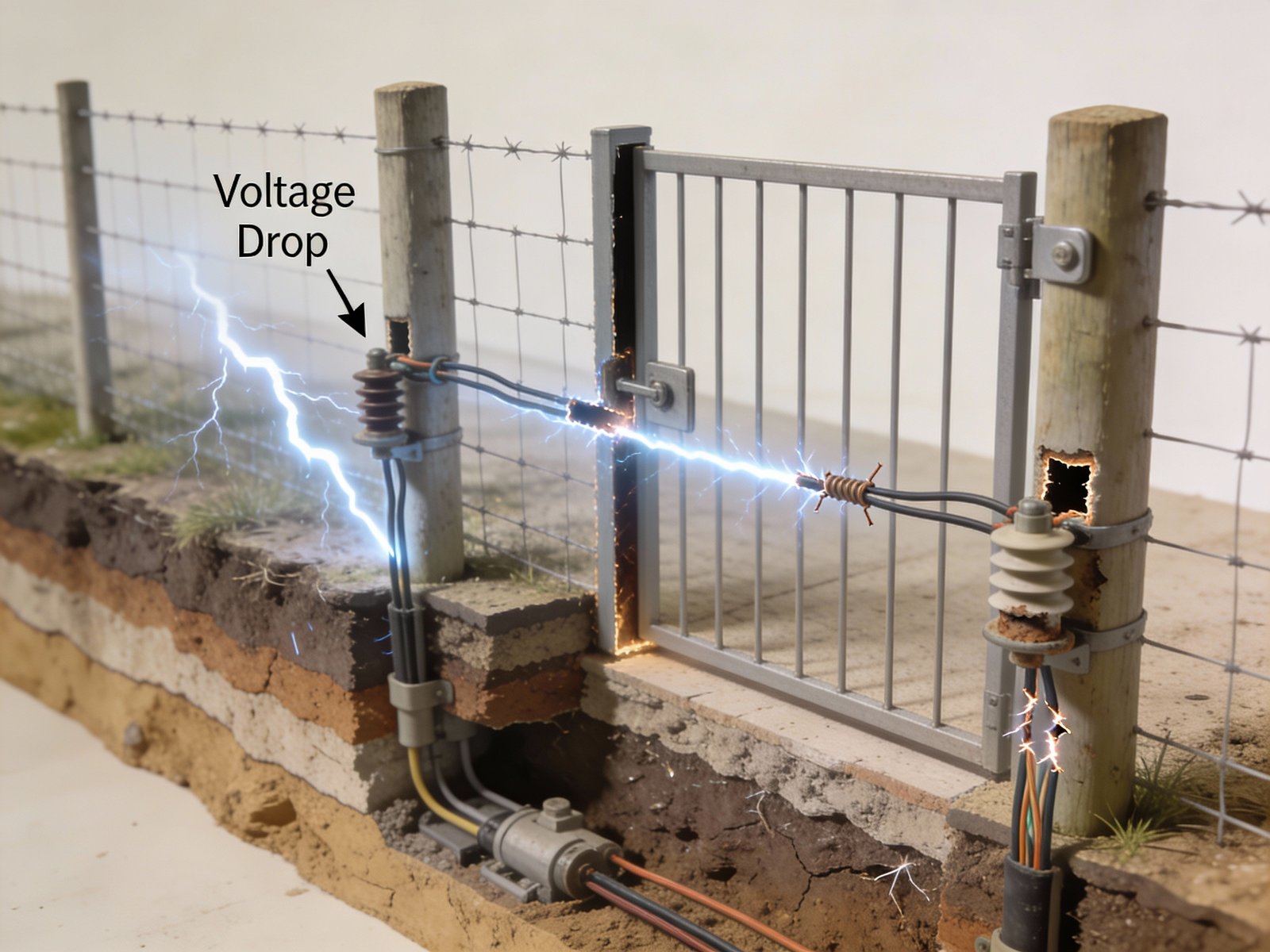
- Resistance buildup: Corrosion at connection points increases electrical resistance, causing voltage drop even when physical continuity appears intact
When gate voltage drops below the effective threshold (typically 2,000-3,000 volts for livestock), animals learn that the gate area is safe to challenge. This creates a localized containment failure that undermines the entire fence system.
Core Design Principles for Electric Fence Gates
Effective gate design balances four competing requirements: electrical performance, mechanical durability, operator safety, and ease of use. Compromising any single factor reduces system reliability.
Electric Fence Gate Types Compared
Gate selection depends on six factors: traffic frequency, gate span width, livestock type, fence voltage, environmental conditions, and operator skill level. Each gate type represents specific engineering tradeoffs.
| Gate Type | Optimal Application | Technical Advantages | Failure Modes & Limitations |
|---|---|---|---|
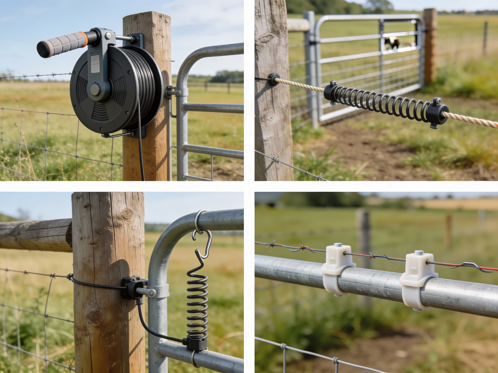
| Auto Retracting Reel Gate | High-frequency access points (10+ uses/day), main farm entrances | Self-tensioning mechanism eliminates slack; automatic retraction reduces user error; consistent conductor tension maintains electrical performance | Spring mechanism fatigues after 2-3 years of daily use; higher initial cost; requires annual inspection of reel pawl and conductor attachment points |
| Elastic Gate Components | Rotational grazing systems, temporary paddock subdivision | Adjustable span (3-8 meters typical); rapid relocation without tools; accommodates ground irregularities | UV exposure degrades elastic after 18-24 months; stretch fatigue reduces tension over time; less effective in sub-freezing temperatures |
| Gate Springs with Insulated Handles | Internal pasture gates, light livestock pressure | Simple hook-on/off operation; low maintenance; minimal components to fail; effective for spans under 4 meters | Spring stretching under heavy livestock impact; inadequate for high-traffic areas; hook mechanism can corrode in coastal/humid climates |
| Electrified Steel Tube Gates | Primary internal access points, equipment passages requiring structural strength | High mechanical strength (supports 200+ kg lateral load); long service life (15+ years); integrates with permanent fencing | Complex installation requiring proper insulation at hinges and latch points; risk of complete fence short if insulator fails; gate must be grounded separately from fence ground system |
| Insulated PVC Gates | Low-voltage applications, areas requiring non-metallic construction | Lightweight (5-8 kg typical); corrosion-immune; low electrical resistance when properly constructed | Limited mechanical strength; UV degradation of PVC after 5-7 years; inadequate for large livestock or equipment impact |
Maintaining Electrical Current Across Gates
Gates interrupt the physical fence conductor but must not interrupt the electrical circuit when closed. Two independent current paths provide redundancy against connection degradation:
Primary Current Path: Gate Conductor
The gate itself carries current through its conductor (wire, tape, or rope). Connection points at both ends must use corrosion-resistant hardware (stainless steel clamps or crimped terminals). These connections are subject to mechanical stress and will degrade—they should not be the sole current path.
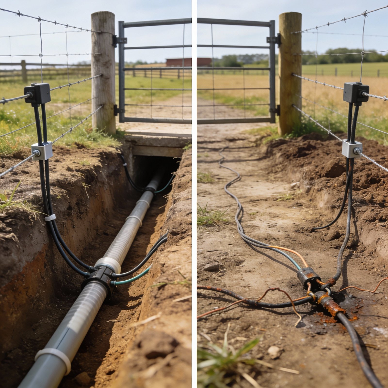
Secondary Current Path: Buried Insulated Lead-Out Cable
An underground jumper cable provides electrical continuity independent of gate condition. This is the critical redundancy that prevents gate failures from becoming system failures.
Underground Cable Installation Requirements
- Cable specification: Minimum 12.5-gauge insulated wire rated for 10,000+ volts (high-density polyethylene or cross-linked polyethylene insulation)
- Burial depth: 18-24 inches to prevent damage from surface traffic and tillage equipment
- Protective conduit: 3/4-inch Schedule 40 PVC conduit at gate opening and where cable rises to fence connection (prevents rodent damage and mechanical stress)
- Connection method: Compression clamps or crimped terminals—never twist-and-tape connections that increase resistance
- Service loop: Provide 12-18 inches extra cable length at each fence connection to allow for future repair without re-trenching
Recommended YouTube Installation Demonstration
This video demonstrates the correct method for installing insulated underground cable beneath an electric fence gate opening. The installer shows proper trenching depth, conduit placement at cable entry/exit points, and secure connection techniques using compression clamps. Key emphasis on avoiding common mistakes such as insufficient burial depth and relying solely on gate conductors for electrical continuity. The demonstration highlights why underground jumper cables are essential for maintaining consistent fence voltage across high-use gate areas.
(Shows grounding rod connection and proper wire routing through PVC conduit)Safety Requirements for Electric Fence Gates
Electric fence gate safety involves both regulatory compliance and practical risk mitigation. Injuries and liability claims most commonly occur at access points where non-agricultural personnel interact with energized systems.
Public Access Prohibition
Gates that cross public roads, designated rights-of-way, shared access easements, or pedestrian paths must never be energized. This prohibition is absolute regardless of signage or warning devices. In jurisdictions where this is not explicitly prohibited by statute, civil liability for electric shock injury is substantially elevated at public access points.
Compliance method: Install de-energized gate with physical barrier (non-electrified steel or wood gate) and use underground jumper cable to maintain circuit continuity on both sides. Gap in physical fence line is acceptable; gap in electrical circuit is not.
Warning Sign and Visibility Requirements
All energized gates must display visible warning signs within 3 meters of the gate opening. Signs must be legible from both approach directions and state: “Electric Fence – Do Not Touch”. Handle assemblies should use high-visibility colors (yellow, orange, or bright red) to differentiate them from surrounding materials.
Rationale: Delivery personnel, emergency responders, and visitors unfamiliar with agricultural operations may not recognize electric fence construction. Visible warnings reduce accidental contact incidents by 70-85%.
Operator Safety Design Features
Gates must be operable with one hand while maintaining safe distance from energized conductors. Insulated handles should be 150-200mm long minimum to ensure hand placement remains isolated from live components. Gate design must not require operator to reach across or through live wires during normal operation.
Failure consequence: Gates requiring two-hand operation or awkward body positioning increase shock risk, especially in wet conditions or when wearing conductive gloves. This leads to operators disabling fence sections rather than using the gate—undermining the entire system.
Common Gate System Problems and Root Causes
Most gate failures result from three underlying issues: inadequate initial design, improper installation, or deferred maintenance. Understanding failure modes enables preventive action.
Best Practices for Reliable Gate Design
Implementing these practices during initial installation prevents 80-90% of gate-related failures and reduces lifetime maintenance requirements.
Gate System Design and Installation Checklist
- Gate type selection: Match gate mechanism to actual usage frequency and span requirements—do not undersize based on cost alone
- Underground jumper cable: Install 12.5-gauge minimum insulated wire beneath every gate opening at 18-24 inch depth with PVC conduit protection at vulnerable points
- Connection hardware: Use only corrosion-resistant compression clamps or crimped terminals—never twist-and-tape connections
- Insulated handles: Specify handles rated for electric fence use with minimum 150mm insulated grip length
- Public access de-energization: Install non-electrified physical barriers at all gates crossing public roads or shared access ways
- Warning signage: Mount visible warning signs within 3 meters of gate on both approach sides
- Monthly inspection protocol: Measure voltage on both sides of closed gate; inspect connection points for corrosion; verify handle insulation integrity; check spring/elastic tension
- Annual maintenance: Replace UV-degraded insulators; re-tension stretched springs; verify underground cable continuity with ohmmeter; lubricate metal hardware with dielectric grease
- Documentation: Photograph gate installation; record component specifications; maintain inspection log with voltage readings
Product Solutions for Common Gate Scenarios
For reliable gate construction in high-tensile fence systems, proper wire selection is critical. High-quality fencing wire maintains electrical conductivity and mechanical strength under repeated stress. Consider these options:
- Fixed Knot Fence — Ideal for perimeter fencing where gates require integration with rigid fence structure
- Hinge Joint Fence — Flexible fence option that accommodates ground irregularities near gate installations
For custom gate system design assistance or technical specifications, contact our technical team for application-specific recommendations.
Frequently Asked Questions
Can gates be electrified safely for operator use?
Yes, when using properly rated insulated gate handles (150mm+ grip length) and provided the gate does not cross public access areas. The insulated handle isolates the operator’s hand from the live conductor. However, underground jumper cables are still required as the primary current path—the gate conductor serves as backup, not the sole electrical connection. Gates crossing public roads or shared access must never be energized regardless of handle type.
Why is fence voltage typically lower at gates than at the energizer?
Voltage reduction at gates occurs due to three factors: (1) Accumulated line resistance from fence conductor over distance, (2) Connection resistance at gate terminals (corrosion increases this over time), and (3) Current leakage if gate components are worn or if inadequate insulation exists. Missing underground jumper cables force all current through gate hardware connections, which have inherently higher resistance than continuous buried wire. A properly installed gate with underground cable should show less than 500V drop from fence line voltage.
Do temporary rotational grazing gates require underground cable?
Yes. The term “temporary” refers to gate location, not installation standards. Even gates relocated monthly require underground jumper cables at each position to maintain electrical continuity. The alternative—relying solely on spring gate or polywire gate conductors—results in 30-50% voltage loss at the gate, creating a known weak point that livestock will exploit. For frequently moved gates, use pre-cut cable sections with quick-connect terminals to reduce installation time to under 15 minutes per relocation.
What is the minimum acceptable voltage at a closed gate?
Minimum effective voltage depends on livestock type: cattle require 2,500V, horses 2,000V, and sheep/goats 4,000V+. However, design target should be 5,000V+ at all points including gates to provide safety margin for vegetation loading and system degradation between maintenance intervals. If gate voltage falls below these thresholds, inspect underground cable continuity, check connection points for corrosion, and verify gate conductor is not broken or severely stretched.
How often should gate systems be inspected?
Monthly voltage measurement (both sides of closed gate) and visual inspection of connections, insulators, and handle condition. Annual maintenance includes ohmmeter testing of underground cable, replacement of UV-degraded components, and re-tensioning of stretched springs. High-traffic gates (10+ uses/day) may require quarterly maintenance. Document inspection results to identify degradation trends before complete failure occurs.
What causes underground cables to fail?
Four primary failure modes: (1) Rodent damage from insufficient burial depth (less than 18 inches), (2) Mechanical stress at cable entry/exit points where no protective conduit was installed, (3) Water infiltration into buried splice connections causing corrosion, (4) Incorrect cable specification—using low-voltage wire not rated for 10kV+ electric fence pulse. Underground cable failures are usually not visible without excavation, making voltage testing across closed gates the only reliable diagnostic method.