
Insulator Selection & Installation for Electric Fencing
How to choose the right insulators and install them correctly for reliable electric fence performance
Why Insulators Matter More Than Most Fence Failures Suggest
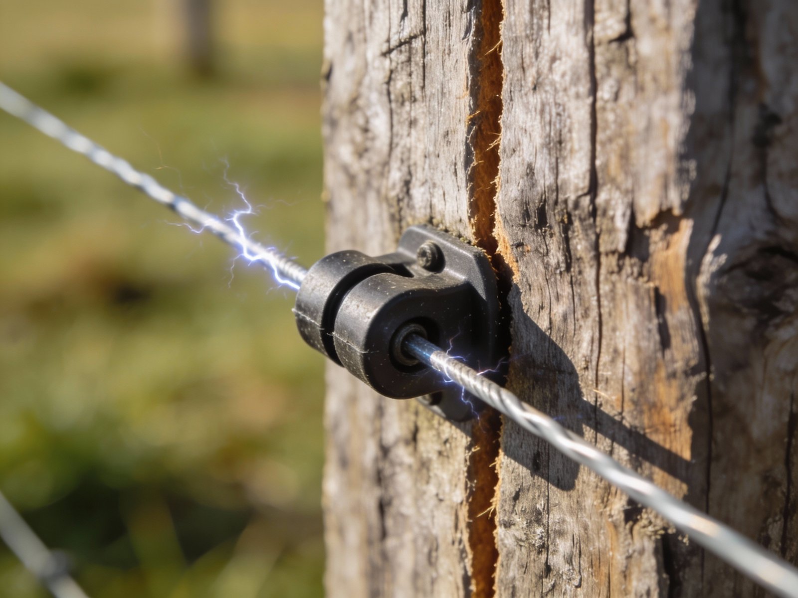
In an electric fencing system, insulators are often treated as small, inexpensive accessories. In reality, they determine whether electricity stays on the wire or leaks into the post and ground. An insulator’s sole engineering purpose is to create a physical barrier between the electrified conductor and any conductive material such as wood, metal, or soil. When this barrier fails or is improperly installed, the result is a direct short circuit that allows high-voltage pulses to dissipate into the earth before reaching animals or intruders.
Poor insulator selection or improper installation leads to voltage loss, inconsistent shocks, and long-term system instability—even when the energizer is properly sized. Electric fence energizers produce voltage pulses exceeding 5,000 volts at low amperage. These high-voltage pulses actively seek the path of least resistance back to the ground system. Without functional insulators, fence posts become that path. Wooden posts contain moisture that conducts electricity, especially during wet conditions. Metal T-posts are inherently conductive and will ground out the fence instantly if wire makes direct contact. The voltage that should travel down the fence line to deliver a corrective shock instead flows into posts, through soil moisture, and returns to the energizer ground rods without ever completing the intended circuit through an animal. This fundamental failure renders even the most powerful energizer ineffective.
Voltage leakage from degraded or missing insulators creates hidden energy drains across the entire fence system. A single cracked insulator allowing wire-to-post contact can reduce line voltage by 1,000 to 2,000 volts in dry conditions and far more when moisture is present. Multiple compromised insulators compound the problem exponentially. What begins as an isolated 500-volt drop at one post cascades into system-wide failure as current finds multiple leak paths. Animals quickly learn which sections deliver weak shocks and exploit those areas. Voltage losses also increase as distance from the energizer grows, making insulator integrity even more critical on long fence runs. Without proper insulation, fence voltage at the far end of a quarter-mile run may drop below the 3,000-volt minimum needed to deter livestock, regardless of energizer output capacity.
The most common mode of insulator failure is material degradation caused by ultraviolet radiation, high-voltage stress, and environmental exposure. Plastic insulators manufactured from inferior polymers or without UV stabilization will crack, become brittle, and eventually disintegrate after one to three years of outdoor exposure. UV radiation breaks down molecular bonds in untreated plastics, creating surface cracks that propagate inward. Once cracks form, moisture infiltrates the insulator body. When voltage pulses pass through the fence wire, electrical arcing occurs across the crack, creating carbon deposits. This process is called carbonization or carbon tracking. Carbon is conductive, so each arc creates a progressively better conductive path from wire to post. Over time, a heavily carbonized insulator becomes nearly as conductive as a metal post, completely defeating its insulating function.
Installation errors contribute as much to fence failure as material defects. Rigid attachment of fence wire to line posts eliminates the elasticity needed to absorb animal impact, wind load, and thermal expansion. When wire is tied tightly to every post using improperly installed insulators, the fence becomes brittle. A single point of failure such as a broken wire or pulled staple propagates along the entire fence line. Proper installation allows wire to float through line post insulators while being anchored only at corners and ends. This floating design distributes stress across the system and prevents catastrophic failures. Insulators must be selected and installed to support this engineering principle or the fence will fail prematurely regardless of material quality.
Insulator Material Comparison: Engineering Properties and Field Performance
Insulators are manufactured from materials with specific dielectric properties, UV resistance characteristics, and mechanical strength profiles. The two primary categories are high-density plastics and ceramic porcelain, each offering distinct advantages depending on fence type, voltage level, environmental exposure, and expected service life. Material selection directly affects electrical insulation performance, resistance to environmental degradation, and mechanical durability under stress.
| Material Type | Advantages | Limitations | Best Applications |
|---|---|---|---|
| Plastic (Polyethylene / Polycarbonate) | Lightweight, UV-resistant when treated, cost-effective, flexible under impact, easy installation, suitable for temporary and permanent fences | May carbonize over time if inferior quality, susceptible to UV degradation without stabilizers, lower mechanical strength than ceramic | Most electric fence applications including livestock containment, rotational grazing, temporary barriers |
| Ceramic (Porcelain) | Extremely durable, long lifespan exceeding 25 years, superior resistance to UV and carbonization, excellent dielectric strength, resists environmental degradation | Heavy, expensive, brittle and prone to breakage during installation or impact, difficult to replace in field conditions | Permanent high-voltage fences, high-tension wire systems, corner and end posts with maximum strain loads |
Plastic insulators manufactured from virgin polyethylene or polycarbonate with UV stabilizers perform reliably for 10 to 20 years in field conditions. Black plastic formulations typically contain carbon black, which acts as a UV absorber and significantly extends service life. White or colored plastics require chemical UV stabilizers to achieve comparable durability. Low-cost insulators made from recycled or reground plastic degrade rapidly, often failing within 18 to 36 months. When purchasing plastic insulators, verify that the product specifies UV-stabilized virgin polymer material. Cheap insulators may appear identical to quality units at purchase but will crack and fail far sooner under field exposure.
Ceramic insulators offer superior electrical performance in high-voltage applications and extreme environmental conditions. Porcelain is non-porous, preventing moisture absorption that can lead to internal electrical tracking. The material is chemically inert and does not degrade under UV exposure, temperature extremes, or prolonged high-voltage stress. However, ceramic insulators are brittle and will shatter if struck by falling branches, machinery, or during rough handling. Installation requires more care, and field replacement is more difficult than plastic alternatives. For permanent perimeter fences where longevity justifies higher initial cost, ceramic insulators provide the longest service life and most reliable electrical isolation.
Selecting Insulators by Post Type and Mechanical Attachment Method
Different fence post materials require specific insulator designs to achieve secure mechanical attachment while maintaining electrical isolation. Post type determines the attachment method, which in turn affects installation labor, long-term reliability, and ability to withstand wire tension and environmental stress.
Wood Posts
- Nail-on insulators: Simple installation but risk splitting wood, especially near post ends or in dry, seasoned wood
- Pin-lock insulators: Threaded or barbed pins that twist into wood, providing secure hold without splitting risk
- Screw-in insulators: Most secure attachment using wood screws or self-tapping designs, ideal for corner and end posts under high tension
Wood posts require insulators that resist splitting and maintain secure attachment over time. Wood expands and contracts with moisture changes, which can loosen nailed insulators. Screw-in designs provide the most reliable long-term attachment, particularly on corner posts where wire tension creates constant pull forces. When installing screw-in insulators, ensure the plastic body does not contact the wood post surface, as moisture between the post and insulator can create a conductive path. The threaded section should be fully engaged in the wood with the insulator body standing off from the post.
T-Posts and Metal Stakes
- Clip-on insulators: Snap onto the post profile using spring tension or fitted clips designed for specific T-post dimensions
- Screw-on insulators: Attach using small screws or bolts through existing T-post holes or self-drilling designs
T-post insulators must fit tightly to prevent rotation and accidental wire contact with the conductive metal post. Loose-fitting clip-on insulators will rotate downward under wire weight or animal pressure, eventually allowing wire-to-metal contact that shorts the fence. Quality clip-on insulators are molded to match specific T-post profiles and create firm mechanical interference that resists movement. Check insulator fit during installation by attempting to rotate the insulator by hand. If it moves easily, select a different design or use screw-on models that lock positively to the post. T-posts conduct electricity instantly, so any wire contact results in total voltage loss at that point.
Corner and End Posts
- Heavy-duty corner insulators: Reinforced designs with increased material thickness and larger wire channels to handle tension loads
- Strain-rated insulators: Engineered for specific load capacities, often with metal reinforcement or larger attachment points
- Wrap-around or W-channel designs: Distribute load around the post circumference rather than concentrating stress at a single attachment point
Corner posts experience the highest mechanical stress in any fence system, as wire tension pulls from multiple directions. Standard line post insulators will fail rapidly under these loads. Corner and end posts require insulators specifically engineered to handle tensile forces ranging from 200 to 600 pounds depending on wire gauge and system design. High-tensile wire fences generate particularly high loads that will pull standard insulators out of wood posts or break plastic bodies. For these applications, use heavy-duty corner insulators rated for the specific wire tension in your system. Many professional installations use double insulators or ring-style designs that distribute load and provide redundancy if one insulator fails.
Chain-Link and Existing Wire Fences
- Standoff insulators: Extend electrified wire away from conductive chain-link mesh using offset arms or extension brackets
- Tube or spacer insulators: Create physical separation between hot wire and grounded fence material
Special standoff insulators are required to isolate electrified wire from conductive metal mesh or existing non-electric wire fencing. Chain-link fences are grounded structures, so any contact between hot wire and mesh creates an immediate short circuit. Standoff insulators mount to chain-link posts and extend the hot wire 6 to 12 inches away from the mesh, preventing contact even when wind blows the wire or animals push against it. When adding electric wire to existing barbed wire or woven wire fences, use tube insulators that maintain clearance and prevent wire-to-wire contact. Installing electric wire directly against non-insulated fence wires defeats the entire system, as the grounded fence will drain all voltage before it reaches an animal.
Key Installation Principles: Engineering for Reliability and Longevity
Proper insulator installation requires understanding the mechanical and electrical engineering principles that govern electric fence performance. Installation errors create hidden failures that manifest as voltage loss, wire breakage, and premature component failure. Following these principles ensures maximum system reliability and service life.
Insulator alignment is critical for maintaining consistent wire height and preventing unintended contact between wires or between wire and posts. When installing insulators on line posts, use a string line or laser level to mark exact placement height. Installing insulators at varying heights creates high and low spots where wires sag or rise, potentially touching each other or vegetation. Multi-wire fences require careful spacing between wires to prevent shorting. Recommended minimum spacing is 6 inches between adjacent hot wires to prevent arc-over in humid conditions or when wires sway in wind.
Insulator installation on corner posts must account for angular wire pull forces. When fence lines change direction, wire tension pulls insulators at an angle rather than straight back. This angular force can pull insulators out of wood or cause plastic bodies to flex and eventually crack. Corner insulators should be installed with the wire channel oriented to align with the resultant force vector, not perpendicular to the post face. For corners with 90-degree turns, this means orienting the insulator at approximately 45 degrees to each fence line. Some corner insulator designs include multiple wire channels allowing the insulator to naturally align with wire forces from different directions.
Using Double-Hole Insulators Correctly: Load Distribution and Failure Prevention
Double-hole insulators are frequently misunderstood and incorrectly installed, leading to premature failure and voltage leakage. Their engineering purpose is to manage force direction and distribute mechanical load across the insulator body through compression rather than tension. When installed correctly, double-hole insulators provide superior strength and longevity compared to single-hole designs in high-stress applications.
Correct Installation Method: Compression Loading
Run the wire through the first hole from the outside, loop it around the back of the insulator, and return it through the second hole, creating a crossing or figure-eight pattern. This configuration compresses the insulator body between the two wire segments rather than pulling the insulator apart. Compression loading distributes stress across the entire plastic structure, which is much stronger than loading the material in tension. The wire essentially clamps the insulator against the post, creating a mechanically stable assembly that resists pull-out forces and distributes wire tension evenly.
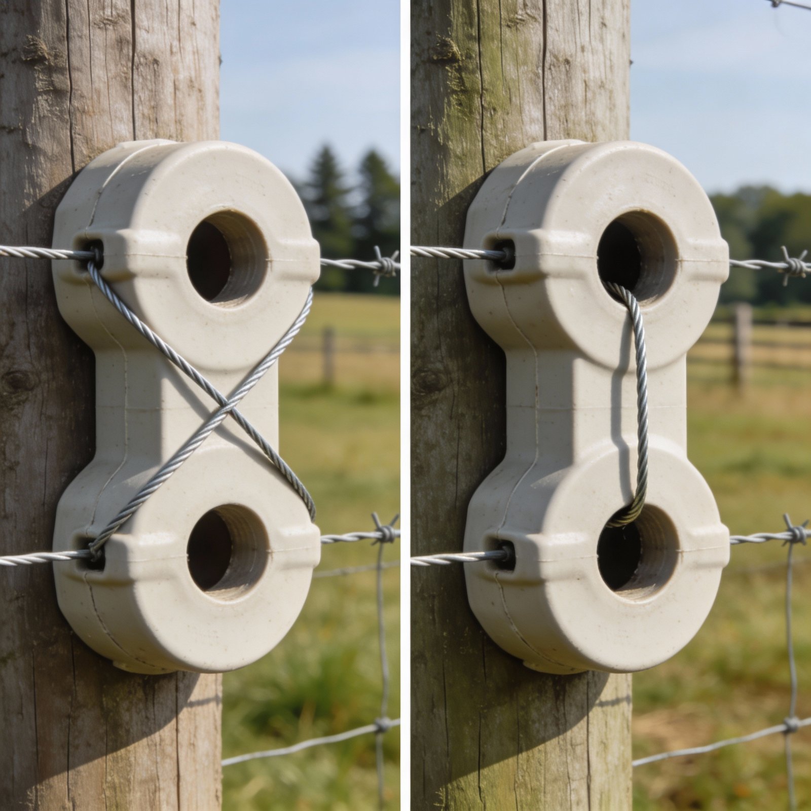
Double-hole insulators are particularly useful on corner posts and high-tension sections where wire forces exceed the capacity of standard single-hole designs. The crossing wire pattern also provides redundancy: if one section of the insulator cracks, the wire remains captured by the second hole, preventing complete failure until the insulator can be replaced. For maximum reliability on critical corners, some installers use two separate double-hole insulators per wire, stacked vertically with a few inches separation. This provides redundant load paths and ensures fence integrity even if one insulator fails completely.
Common Insulator Selection and Installation Mistakes That Cause System Failure
Most electric fence failures attributed to energizer problems or grounding issues are actually caused by insulator defects or installation errors. Recognizing and avoiding these common mistakes prevents voltage loss, reduces maintenance costs, and extends fence system service life.
The most insidious insulator failure mode is partial degradation that reduces but does not eliminate fence voltage. A fence operating at 2,500 volts due to multiple compromised insulators may appear functional and deliver mild shocks, but will not effectively contain determined animals. Livestock quickly learn to tolerate weak shocks and will push through low-voltage sections. Measuring fence voltage at multiple points along the line, particularly at locations farthest from the energizer, reveals these hidden leaks. Any voltage reading below 3,000 volts indicates inadequate fence performance that requires immediate troubleshooting. Systematically checking insulator condition during voltage testing often reveals multiple degraded units that collectively drain system performance.
Installation errors often stem from misunderstanding electric fence engineering principles. Many installers with experience in barbed wire or woven wire fences apply those techniques to electric fences, not recognizing that electric fences require fundamentally different mechanical design. Barbed wire fences rely on rigid wire tension and frequent attachment points to create physical barriers. Electric fences rely on psychological deterrence through shock delivery and require floating wire systems with minimal attachment points to maintain voltage. Applying barbed wire installation methods to electric fences creates rigid, brittle systems that fail mechanically and electrically. Understanding this fundamental difference prevents most common installation errors.
Inspection and Maintenance of Insulators: Preventing Hidden Failures
Regular insulator inspection is essential for maintaining fence performance and preventing gradual voltage degradation that allows animals to escape. Many insulator failures develop slowly over months or years, creating progressive performance loss that goes unnoticed until the fence becomes completely ineffective.
- Inspect insulators during routine fence voltage testing, checking for visible cracks, discoloration, or carbon tracking marks that indicate electrical arcing
- Replace cracked or carbonized units immediately, as these create conductive paths even when mechanically intact and will progressively worsen
- Check insulator alignment and mechanical attachment after storms, heavy snow loads, or livestock pressure events that may have shifted posts or loosened attachments
- Monitor T-post insulators for rotation or downward slippage that allows wire contact with metal posts, creating immediate short circuits
- Examine corner and end post insulators for stress cracks around attachment points where wire tension concentrates mechanical loads
- Clean insulators in areas with heavy dust, pollen, or agricultural chemical exposure, as conductive surface contamination can create voltage leakage paths
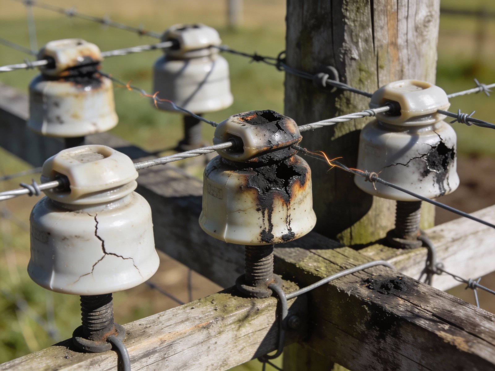
Carbon tracking appears as dark streaks or spots on insulator surfaces, particularly around wire contact points or between the insulator body and mounting hardware. These marks indicate electrical arcing has occurred, depositing conductive carbon that creates a progressively better leakage path with each subsequent arc. Once carbon tracking begins, it accelerates rapidly as the conductive path allows more current flow, creating more arcing and additional carbon deposition. Insulators showing any carbon tracking should be replaced immediately, as they will continue to degrade and leak increasing amounts of voltage. Surface cleaning does not remove carbon deposits embedded in plastic cracks and pores.
Systematic fence inspection should follow a methodical approach to identify all insulator problems efficiently. Begin by measuring fence voltage at the energizer output, then at quarter-length intervals along the fence line, and finally at the point farthest from the energizer. Significant voltage drops between measurement points indicate problems in that section. Walk that section carefully, checking each insulator for damage, wire contact with posts, or vegetation touching wires. Using a voltage meter to probe individual wire segments can isolate specific problem areas. When you find one damaged insulator, check adjacent units carefully, as similar environmental exposure or installation errors often affect multiple insulators in the same section.
System Integration: How Insulators Interact with Energizers, Grounding, and Overall Fence Performance
Insulators function as one component in an integrated electric fence system where performance depends on proper interaction between the energizer, fence wire, grounding system, and insulation. Understanding these interactions is essential for diagnosing problems and optimizing total system performance.
The energizer produces high-voltage pulses that travel down the fence wire seeking the path of least resistance back to the energizer ground rods. In a properly functioning system, this path is through an animal touching both the fence wire and the earth, completing the circuit. Degraded insulators create alternative return paths through fence posts and soil, allowing voltage to bypass animals and return directly to ground. This reduces the voltage available at the fence wire and decreases shock intensity delivered to animals. Even a powerful energizer cannot overcome multiple insulator failures that create low-resistance short circuits draining system voltage.
Grounding system effectiveness directly affects how insulator failures manifest. An inadequate grounding system with insufficient ground rods or poor soil conductivity may partially mask insulator problems by limiting the current that can flow through leakage paths. However, this is false security, as the fence performs poorly both due to inadequate grounding and insulator leakage. Conversely, a properly designed grounding system with excellent soil contact will allow compromised insulators to drain maximum current, causing severe voltage drops that reveal the problem. This is actually beneficial, as it makes insulator failures immediately obvious through voltage testing rather than allowing gradual, unnoticed performance degradation. For comprehensive information on grounding design, see our guide on grounding system design and testing.
The relationship between insulators and energizer sizing is often misunderstood. A common error is purchasing a larger energizer to compensate for voltage losses caused by poor insulators or vegetation contact. While higher energizer output can partially overcome minor leakage, it does not address the root cause and wastes energy maintaining voltage in a defective system. The correct approach is to eliminate all leakage sources through proper insulator maintenance and vegetation control, allowing a properly sized energizer to deliver maximum voltage efficiently. This produces better animal deterrence with lower energy consumption and equipment cost.
Common installation mistakes often involve interactions between multiple system components. For example, running lead-out wire from the energizer to the fence without proper insulation creates voltage leakage before the current even reaches fence insulators. Using undersized fence wire increases resistance, creating voltage drops that compound insulator leakage losses. Installing an energizer too far from the fence center point creates unequal voltage distribution that makes insulator problems at distant fence sections more severe. For a comprehensive overview of avoiding these interconnected errors, consult our guide on common electric fence installation mistakes.
Educational Resources: Understanding Insulator Function and Troubleshooting Voltage Loss
Video demonstrations provide valuable insight into proper insulator installation techniques and troubleshooting methods that are difficult to convey through text alone. The following resource offers practical field guidance on why insulator installation quality directly affects fence performance.
Why Proper Insulator Installation Is Critical for Electric Fences
This video demonstrates correct and incorrect installation techniques for reel insulators, showing how improper installation allows wire-to-post contact that grounds the fence. The presenter explains why insulators must be fully secured with adequate wraps and positioned to prevent wire slippage, particularly important in corner and sweep sections where wire angles create complex forces. The demonstration clearly shows how a properly installed insulator protects the wire from contact with metal post components, while improper installation allows the wire to slide down and rest against conductive surfaces, creating voltage leakage.
Video: Why proper Insulator installation is so important for electric fences – Tracking Y Ranch
Key Takeaways from Video:
- Reel insulators must be installed with the wire threading through the insulator in the correct pattern to prevent slippage
- Improper installation allows wire to slide down and contact metal post components, especially in wet conditions, creating direct shorts
- The demonstration shows side-by-side comparison of correct installation with secure wire protection versus incorrect installation where wire rests against grounded metal
- Proper installation maintains electrical isolation regardless of wire tension, weather conditions, or minor fence movement
- Visual inspection can identify improperly installed insulators by checking whether wire maintains clearance from all conductive post surfaces
Understanding the physics of voltage leakage helps diagnose complex fence problems. When multiple factors contribute to voltage loss, systematic troubleshooting requires isolating each component. Start by disconnecting the fence from the energizer and measuring insulation resistance using a digital multimeter set to high resistance range. A properly insulated fence with all wires isolated from posts should show infinite or extremely high resistance between fence wire and ground. Any measurable resistance indicates leakage paths through compromised insulators, vegetation contact, or wire damage. This test can be performed on isolated fence sections to locate problem areas.
For additional guidance on maintaining overall electric fence system performance, including seasonal inspection schedules and component replacement intervals, see our comprehensive maintenance guide. Integrating insulator inspection into regular maintenance protocols prevents minor degradation from becoming major system failures.
Frequently Asked Questions
Do ceramic insulators perform better than plastic insulators electrically?
Ceramic and high-quality plastic insulators offer essentially identical electrical insulation performance when new. Both materials have dielectric strength exceeding electric fence voltage requirements by large margins. The practical difference lies in mechanical durability and environmental resistance over time. Ceramic insulators maintain electrical performance for decades without degradation, while plastic insulators may develop cracks or carbonization that creates leakage paths after 10 to 20 years depending on quality and UV exposure. For permanent installations where maximum service life justifies higher initial cost, ceramic offers superior long-term performance. For most livestock fencing applications, UV-stabilized plastic insulators provide excellent electrical performance at lower cost and with easier installation and field replacement.
How far apart should line posts be spaced for optimal fence performance?
Line post spacing typically ranges from 12 to 20 feet depending on terrain, wire type, animal species, and expected pressure on the fence. High-tensile wire fences can support 15 to 20 foot spacing on level terrain with minimal animal impact. Poly wire and poly tape require closer spacing of 12 to 15 feet to prevent excessive sagging between posts. Rough or hilly terrain requires closer post spacing to maintain consistent wire height. Areas where animals congregate or push against fences benefit from 10 to 12 foot spacing to distribute pressure. The optimal spacing balances material and labor costs against performance requirements. Excessively close spacing increases costs without improving performance, while excessively wide spacing allows wire sag and increases stress on each insulator.
Should fence wires be pulled tight on line posts or allowed to move freely?
Fence wires should move freely through line post insulators without being tied, clamped, or rigidly fastened. This floating design is fundamental to electric fence engineering and serves multiple critical functions. Free-moving wire absorbs impact from animals or falling debris by distributing stress along the entire wire length rather than concentrating it at fixed attachment points. Wire that can slide through insulators accommodates thermal expansion and contraction without building dangerous tension that breaks wires or pulls insulators from posts. The floating design also allows temporary fence deformation from animal pressure to recover elastically after the load is removed. Only corner posts, end posts, and gate anchors should have wire rigidly attached using tensioners or strain insulators. All intermediate line posts must allow wire movement to prevent mechanical failure and premature component wear.
What causes insulators to develop carbon tracking and how can it be prevented?
Carbon tracking results from electrical arcing across cracks or contaminated surfaces on insulator bodies. The process begins when UV exposure, mechanical stress, or manufacturing defects create hairline cracks in plastic insulators. High-voltage fence pulses arc across these cracks, depositing conductive carbon from decomposed plastic. Each arc deposits more carbon, creating a progressively better conductive path that allows stronger subsequent arcs. This positive feedback loop rapidly degrades the insulator until it leaks substantial current. Prevention requires using UV-stabilized insulators manufactured from quality materials, proper installation that minimizes mechanical stress, and regular inspection to identify early-stage cracks before carbon tracking begins. Once carbon tracking is visible, the insulator must be replaced, as surface cleaning cannot remove carbon embedded in cracks and pores.
Can I add electric wire to an existing barbed wire or woven wire fence using insulators?
Yes, electric wire can be added to existing non-electric fences using standoff or offset insulators that maintain clearance between the hot wire and grounded fence material. Standard barbed wire and woven wire fences are electrically grounded through posts and ground contact. Any contact between hot wire and these grounded materials creates an immediate short circuit. Standoff insulators mount to existing fence posts and extend the electric wire 6 to 12 inches away from the fence plane, preventing contact even during wind or animal pressure. This configuration is commonly used to reinforce aging fences or modify existing barriers for different animal species. For chain-link or other metal mesh fences, special offset brackets are required to maintain adequate clearance from the conductive mesh. Never install electric wire directly against non-insulated fence wires or mesh, as this defeats the entire electric fence system.
How do I know when insulators need replacement before they fail completely?
Replace insulators showing any of these warning signs: visible cracks in plastic bodies, dark carbon tracking marks around wire contact points, discoloration indicating UV degradation, loose mechanical attachment to posts, deformation or warping of plastic components, brittleness when pressed, or measurable voltage drop across the insulator location. Many of these symptoms appear well before complete failure, providing opportunity for preventive replacement. During routine fence voltage testing, if voltage drops significantly between measurement points, inspect all insulators in that section carefully for early-stage degradation. Preventive replacement of questionable insulators costs far less than troubleshooting mysterious voltage losses or recovering escaped livestock. Establish a scheduled inspection program examining all insulators annually, with more frequent checks on corners, ends, and high-stress sections.
Key Takeaways for Insulator Selection and Installation
Insulators represent a critical control point where small investment in quality components and proper installation techniques produces disproportionate improvements in total system performance. The engineering principle is straightforward: insulators must prevent all unintended current paths from fence wire to ground. Any leakage through compromised insulators directly reduces voltage available for animal deterrence and compromises fence effectiveness regardless of energizer capacity.
Material selection should prioritize UV-stabilized virgin plastic for most applications, with ceramic reserved for permanent high-stress installations where maximum service life justifies higher cost. Installation must allow wire to float through line posts while rigidly anchoring only corners and ends. Double-hole insulators must be installed in crossing patterns that load the material in compression rather than tension. Regular inspection identifies degradation before complete failure, allowing preventive replacement that maintains consistent fence performance.
Understanding insulator function within the complete fence system enables effective troubleshooting and optimization. Voltage losses from insulator failures interact with energizer output capacity and grounding system effectiveness to determine total fence performance. Addressing insulator problems as part of systematic fence design and maintenance produces reliable livestock containment with minimum energy consumption and equipment cost.
For comprehensive electric fence system design guidance including energizer selection, grounding optimization, and integration of all components, see our complete guide on installing electric cattle fences. Understanding how insulators fit within total system design enables informed decisions that maximize performance while controlling costs.