
Wire Spacing and Tension Design for Woven Wire Fence Systems
Executive Summary: Why Spacing and Tension Are Engineering Variables
Wire spacing and post spacing are interdependent engineering variables in woven wire fence design, not arbitrary construction decisions. Proper fence wire spacing and tension levels must be calculated based on wire mechanical properties, knot type structural behavior, and environmental loading conditions. Modern woven cattle fence systems require understanding how wire tensile strength, knot configuration, and galvanized coating corrosion resistance collectively determine the permissible spacing-tension envelope for long-term performance.
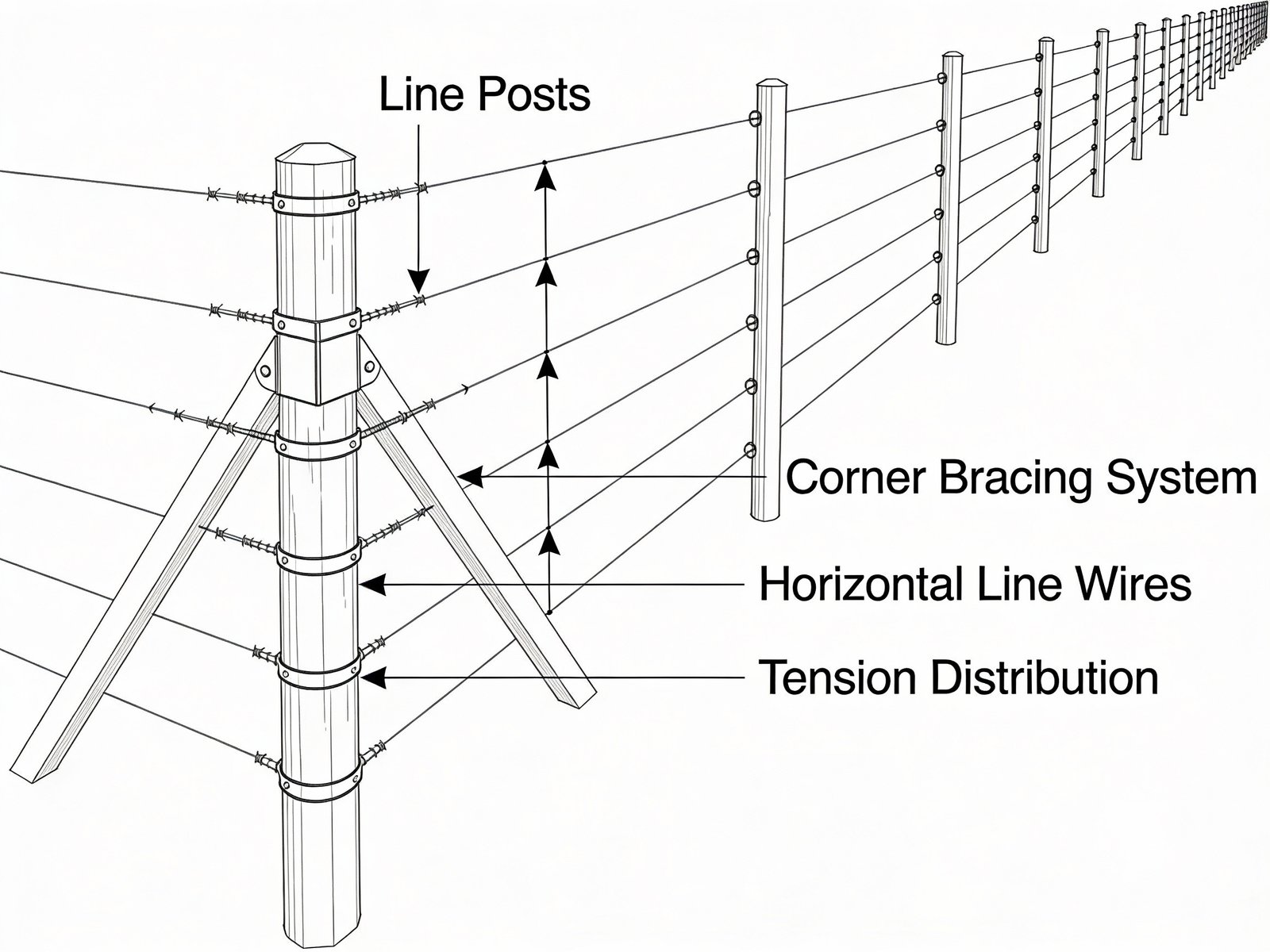
Post spacing for woven wire fence installations typically ranges from 8 feet to 20 feet depending on wire grade and tension capacity. High-tensile wire fencing supports wider post spacing at 16 to 20 feet with tension levels of 200 to 250 pounds per wire, while low-carbon wire requires closer spacing at 8 to 12 feet with conservative tension limits of 150 to 200 pounds. Fixed-knot fence systems demand high wire tension for structural stability, whereas hinge-joint configurations function optimally with moderate tension that preserves knot flexibility. Recommended tension ranges vary by woven wire fence grades: low-carbon wire at 150 to 200 pounds maximum, high-tensile wire at 200 to 250 pounds optimal, and premium tensile grades at 250 to 300 pounds structural limit. These values represent working stress levels that maintain elastic wire behavior, prevent galvanized coating damage, and ensure 30 to 50 year service life under agricultural loading conditions.
The engineering assumptions in this specification build on implementation procedures documented in the woven wire fence installation guide, where field tensioning protocols and post placement sequences are specified for various system configurations.
Why Standard Spacing Fails in Real Installations
The failure of standardized spacing recommendations stems from their inability to account for system-level interactions in woven wire fence design. A fixed-knot fence using 12.5-gauge high-tensile wire with breaking strength of 1,380 pounds per wire can sustain 20 to 30 foot post spacing under controlled tension, while an identical spacing applied to hinge-joint construction with low-carbon wire leads to progressive sagging and joint failure within months. The mechanical behavior differs fundamentally: high-tensile wire elongates only 2 to 4 percent before yield compared to 14 percent for low-carbon wire, meaning tension losses from thermal cycling, creep, and animal impact manifest differently across wire grades.
Environmental variables further invalidate universal standards. Thermal expansion coefficients for steel wire at approximately 12.1 multiplied by 10 to the negative sixth power per degree Celsius generate tension fluctuations of 32 to 86 kilograms per 28 degree Celsius temperature change depending on wire diameter. A 200-meter fence span experiences differential wire elongation between seasons that would be absorbed elastically in high-tensile systems but causes permanent deformation in low-carbon installations. This necessitates engineering design rather than pattern replication. Spacing and tension must be calculated as functions of wire mechanical properties, knot load distribution, and site-specific conditions.
Fence Tension Mechanics in Woven Wire Fence Design
Fence wire tension functions as a continuous structural load system rather than a one-time installation parameter. Each horizontal line wire under tension generates compressive forces on posts and lateral loads on corner bracing assemblies. For a woven wire fence tensioned to 250 pounds per wire with seven horizontal lines, corner posts resist cumulative forces exceeding 1,750 pounds attempting to pull them from the ground. This load remains constant over the fence operational life and increases when external forces such as animal impact, wind pressure, or thermal contraction add to baseline tension.
The long-term nature of this loading subjects wires to creep deformation, a time-dependent strain process where materials elongate under constant stress below their yield point. High-tensile wire with 0.28 percent minimum carbon content exhibits superior creep resistance compared to low-carbon alternatives, maintaining dimensional stability under sustained loads that would cause progressive sagging in standard wire. Fatigue cycling from repeated thermal expansion-contraction and animal pressure further differentiates wire performance. Studies on high-strength steel wires demonstrate that tensile stress at 70 percent of ultimate strength accelerates surface film deterioration and reduces corrosion resistance, establishing practical tension limits below theoretical material capacity. Long-term performance expectations under various loading conditions are documented in the woven wire fence lifespan durability analysis.
Thermal cycling introduces additional mechanical complexity. Fence wires experience temperature ranges from negative 30 degrees Celsius to positive 50 degrees Celsius in agricultural environments, generating stress fluctuations of 170 to 190 pounds in 2.5 millimeter high-tensile wire for a 28 degree Celsius temperature swing. These cyclic loads accumulate micro-damage through creep-fatigue interaction, where alternating stress reduces time-to-failure compared to pure creep or pure fatigue loading independently. Proper tension design must therefore balance initial wire stress against long-term degradation mechanisms to ensure woven wire fence lifespan over 20 to 50 year service periods.
Elastic Versus Plastic Behavior in Fence Wires
The elastic-plastic transition point, known as yield strength, represents the critical threshold separating recoverable and permanent wire deformation. Below the yield point, typically 75 to 80 percent of ultimate tensile strength, wires elongate proportionally to applied load and return to original length when stress is removed. High-tensile wire with 200,000 pounds per square inch tensile strength reaches yield around 160,000 pounds per square inch, allowing elastic energy absorption that enables fence flexure under animal impact without permanent damage.
Exceeding yield strength causes plastic deformation, which is permanent wire elongation that cannot be recovered through retensioning. For 12.5-gauge high-tensile wire, this occurs at approximately 280 to 365 kilogram tension depending on woven cattle fence wire grades and manufacturing process. The practical consequence is irreversible fence loosening: once wire yields, subsequent thermal contraction cannot restore original tension, necessitating complete wire replacement or acceptance of reduced performance. This explains why over-tensioning during installation proves more destructive than conservative tensioning. The former locks in permanent deformation while the latter preserves elastic response capacity.
Wire diameter critically influences elastic behavior through its effect on elongation rate. For identical loads, 12.5-gauge wire with 2.51 millimeter diameter elongates twice as much as 9-gauge wire with 3.76 millimeter diameter, providing greater elastic travel before reaching yield. This relationship creates a counterintuitive design principle: lighter-gauge high-tensile wire often outperforms heavier low-carbon wire in tension retention because superior yield strength and elastic range compensate for reduced cross-sectional area. The engineering analysis must therefore evaluate wire grade mechanical behavior rather than relying solely on gauge number as a strength indicator.
Post Spacing Design Principles for Woven Wire Fence
Post spacing functions as a mechanical amplifier for wire loads through geometric relationships between span length and lateral deflection forces. When an animal applies 300 pounds lateral force mid-span between posts, the resulting wire tension increase varies dramatically with spacing: 6-foot spacing generates approximately 364 kilograms additional tension per wire, while 12-foot spacing produces only 273 kilograms for identical deflection distance. This inverse relationship occurs because longer spans allow greater wire elongation to distribute the applied force, reducing instantaneous stress concentration.
However, this mechanical advantage has operational limits. The theoretical calculation assumes elastic wire behavior, but field conditions introduce complications. A 30 centimeter lateral deflection on a 6-meter span between posts creates 5 millimeters per meter wire elongation when staples hold wire tightly to posts, requiring 537 kilograms additional tension, well above the elastic limit for most fence wires. If staples allow wire movement, common in properly installed fences, the same deflection distributes across 200-meter strain sections, reducing elongation to 0.15 millimeters per meter and tension increase to only 16 kilograms. This demonstrates why spacing decisions must account for entire fence system design, not isolated post-to-post segments.
Corner and brace assemblies face amplified loads from wide post spacing. Each line post transfers lateral wire forces to adjacent posts, creating cumulative stress that concentrates at directional changes. A woven wire fence with 25-foot post spacing and seven wire strands tensioned to 250 pounds each generates over 1,750 pounds horizontal force at corners. Inadequate brace design, particularly steep brace wire angles exceeding 30 degrees from horizontal, converts this horizontal force into vertical uplift, pulling corner posts from the ground. This failure mode explains why aggressive post spacing reduction at corners to 6 to 10 feet proves necessary even when line spans reach 20 to 30 feet.
Typical Post Spacing Ranges by Fence System
Hinge-joint fence systems accommodate wider post spacing at 12 to 16 feet for standard wire, up to 16 to 20 feet for high-tensile configurations, because the knot design permits controlled wire movement that distributes loads across multiple joints. The wrapped stay wire configuration allows horizontal displacement without knot failure, functioning as a mechanical cushion that absorbs impact energy. This inherent flexibility enables hinge-joint fences to conform to terrain undulations and accommodate animal pressure without demanding maximum wire tension. Typical installations use 8 to 12 foot spacing in rolling terrain and extend to 16 feet on level ground with properly braced corners.
Fixed-knot systems require tighter integration between spacing and tension because the rigid knot locks stay wires to line wires, preventing independent movement. This structural rigidity demands high-tensile wire to prevent joint failure under load. Combining fixed knots with low-carbon wire creates stress concentrations that cause premature knot breakage. Post spacing for fixed-knot fences typically ranges from 12 to 20 feet on level terrain, reducing to 8 to 12 feet in rough topography where terrain-induced stress variations would otherwise overload knots. The design dependency is absolute: wide spacing requires high wire tension for sag prevention, but high tension necessitates high-tensile wire grade to avoid plastic deformation, creating an integrated spacing-tension-grade specification.
S-knot configurations occupy an intermediate position with moderate load distribution characteristics between hinge-joint flexibility and fixed-knot rigidity. The smooth knot design, lacking barbs or sharp projections, provides safer livestock contact while maintaining reasonable vertical strength. Post spacing recommendations typically fall in the 10 to 14 foot range, though specific products may vary based on wire gauge and coating specifications. The critical engineering consideration remains consistent across all knot types: spacing cannot be selected independently from wire grade and target tension without risking either over-tensioned wire failure or under-tensioned fence sagging.
Wire Tension Levels: How Much Is Enough
Recommended Tension Ranges by Wire Grade
Recommended tension range for woven wire fence varies by wire grade and mechanical properties. Low-carbon wire fencing operates within narrow tension windows constrained by inferior mechanical properties. With ultimate tensile strengths of 60,000 to 80,000 pounds per square inch and yield points around 45,000 to 60,000 pounds per square inch, low-carbon wire tolerates maximum working tensions of 150 to 200 pounds to maintain adequate safety margins below yield. These conservative values prevent plastic deformation but limit sag control. Longer spans inevitably droop between posts, necessitating closer post spacing at 8 to 12 feet maximum to maintain fence geometry. The economic trade-off proves unfavorable: reduced material cost for wire is offset by increased post quantity and installation labor.
High-tensile wire with minimum 200,000 pounds per square inch ultimate strength and 0.28 percent carbon content supports tension ranges of 200 to 250 pounds while maintaining elastic behavior. This elevated working stress, 50 to 75 percent higher than low-carbon wire, enables proportionally wider post spacing and superior sag resistance. Field installation protocols using tension springs calibrated to 150 to 250 pound indicators provide visual confirmation of proper tensioning. The spring compression distance, typically 9 inches relaxed to 7 inches at 250 pounds, or notched indicators at 150 pound and 250 pound thresholds, allows installers to verify tension without specialized equipment. Exceeding 250 pounds tension enters the strain-hardening region where wire begins permanent elongation, sacrificing long-term dimensional stability for marginal short-term tautness.
Premium high-tensile wire grades with 220,000 to 250,000 pounds per square inch ultimate strength extend the operational envelope to 250 to 300 pounds tension, though practical applications rarely exploit this full range. The limiting factor shifts from wire yield strength to corner brace capacity and coating integrity under high stress. Galvanized coatings experience accelerated damage when substrate wire exceeds 70 to 80 percent of ultimate strength due to stress-corrosion cracking mechanisms that compromise the protective zinc layer. Conservative design practice limits working tension to 250 pounds even for premium wire, preserving galvanized coating corrosion resistance and extending service life beyond the 3 to 5 year advantage gained from aggressive tensioning.
Consequences of Over-Tensioning
Over-tensioning initiates a cascade of structural failures beginning with corner assembly overload. Brace systems designed for 250 pound wire loads experience force multipliers approaching 1.5 to 2 times design values when tension reaches 350 to 400 pounds, causing post pullout, brace wire failure, or horizontal rail buckling. The brace wire angle to ground proves critical: assemblies with steep angles exceeding 30 degrees convert horizontal fence tension into vertical uplift forces that extract posts even from well-compacted soil. Field observations confirm that 98 percent of corner failures result from excessive wire tension combined with inadequate brace geometry rather than post rot or material defects.
Coating damage under high tension accelerates corrosion through multiple mechanisms. Galvanized zinc coatings develop microcracks when substrate steel approaches yield strength, creating pathways for moisture penetration to the base metal. Stress-corrosion cracking, a synergistic failure mode combining mechanical stress and environmental attack, occurs specifically in high-strength steel wires under sustained tension exceeding 60 to 70 percent of ultimate capacity. Laboratory testing demonstrates that wires loaded to 70 percent of fracture strength and exposed to corrosive environments exhibit substantially reduced electrochemical impedance and accelerated surface film deterioration compared to unstressed controls. The practical consequence is that aggressively tensioned fences sacrifice 30 to 50 percent of design life through premature coating failure and substrate corrosion.
Wire elongation from over-tensioning creates permanent dimensional changes that prevent retensioning. When installation tension exceeds yield strength, even briefly, plastic deformation occurs. The wire stretches permanently and cannot recover original length upon stress removal. Subsequent thermal contraction during cold weather cannot restore fence tautness because the wire has been metallurgically altered. This manifests as chronically loose fences that require complete wire replacement rather than simple retensioning. The economic impact proves severe: improper initial tensioning converts a 50-year fence asset into a 10 to 15 year consumable requiring premature replacement at costs approaching new installation.
Spacing and Tension Interaction with Knot Types
Fixed Knot: Why Wide Spacing Depends on Tension Stability
Fixed-knot fence structural behavior depends fundamentally on maintaining stable high tension because the rigid knot configuration cannot accommodate wire movement to distribute loads. The knot consists of separate wire twisted under pressure around both horizontal line wire and vertical stay wire, creating a mechanically locked joint with exceptional vertical holding strength. Tests show fixed knots maintain integrity under pressures sufficient to cause wire failure rather than knot separation. However, this structural advantage requires continuous wire tension above 200 pounds to prevent stay wire buckling and loss of fence geometry.
The tension-spacing dependency becomes apparent through load analysis. At 12-foot post spacing with 250 pound wire tension, mid-span deflection from 200 pound animal pressure generates manageable stress increases that remain within elastic limits. Doubling spacing to 24 feet with identical initial tension allows greater wire sag, increasing animal-induced stress to levels approaching or exceeding yield strength. The fixed knot inability to redistribute this localized stress through joint movement means the entire load concentrates at the impact point, risking permanent wire deformation. Consequently, installations combining wide spacing with fixed knots must use premium high-tensile wire with minimum 200,000 pounds per square inch ultimate strength tensioned to 225 to 250 pounds. Any reduction in wire grade or initial tension invalidates the wide spacing assumption.
Tension curve management during installation proves critical for fixed-knot longevity. The horizontal line wires contain manufactured crimps, tension curves, that allow controlled elongation as tension increases. Best practice dictates removing only 50 percent of visible crimp depth during initial tensioning. Extracting more than half risks entering the plastic deformation region where wire begins permanent stretching. Visual verification requires installers to assess crimp depth before and during tensioning, stopping when approximately half the wave amplitude remains. This conservative approach preserves elastic capacity for thermal expansion-contraction cycles and long-term creep accommodation without requiring retensioning over the fence operational life.
Hinge Joint: Controlled Slack as a Design Feature
Hinge-joint knot fence design intentionally incorporates mechanical flexibility through wrapped stay wire configuration that allows limited wire movement under load. The vertical stay wire wraps completely around each horizontal line wire, creating a hinged connection rather than rigid lock. This design permits horizontal displacement when animals contact the fence, distributing impact energy across multiple knots and preventing stress concentration at individual joints. The mechanical behavior resembles a spring system where controlled deflection absorbs energy rather than transmitting it as peak loads to posts and braces.
The slack in hinge-joint fences is not installation error but engineered displacement capacity. When properly installed at 150 to 200 pound tension, the fence can deflect 6 to 12 inches mid-span between posts and return to original geometry without permanent deformation. This elastic response requires lower initial tension than fixed-knot systems precisely because the knot design allows load distribution through wire movement. Over-tensioning hinge-joint fences, exceeding 250 pounds, eliminates this beneficial flexibility, converting the system into a rigid structure that lacks the strength characteristics of properly engineered fixed-knot installations while sacrificing the impact absorption capability of correct hinge-joint design.
Terrain conformability represents another advantage of hinge-joint flexibility. The knot ability to accommodate differential wire heights allows fence installation across rolling topography without requiring perfectly level grade following. Two-way tension crimps in horizontal wires permit expansion and contraction as the fence traverses hills and valleys, maintaining consistent geometry despite elevation changes. This terrain adaptability enables installations in locations where fixed-knot fences would require extensive ground preparation or frequent bracing to prevent stress concentrations at slope transitions. The engineering trade-off favors hinge joints for rough terrain applications and fixed knots for maximum security with minimal post spacing on level ground.
S-Knot: Intermediate Load Distribution Behavior
S-knot configurations provide intermediate mechanical characteristics between fixed-knot rigidity and hinge-joint flexibility through their smooth, continuous stay wire design. The vertical stay wire forms an S-shaped curve around each horizontal line wire, creating a contact joint without the sharp bends or wrapped sections characteristic of other knot types. This geometry allows limited wire movement under load, more than fixed knots but less than hinge joints, producing moderate load distribution capabilities suitable for general livestock applications without extreme pressure conditions. The behavior of these systems in distributed loading scenarios is further detailed in the S-knot fence load distribution reference.
The smooth knot surface distinguishes S-knot fences in livestock safety applications where animal contact with fence elements presents injury risks. Without barbs, sharp twists, or protruding wire ends, the fence surface minimizes wool catching in sheep operations and reduces hide damage in cattle production. This safety advantage does not compromise structural performance significantly: properly tensioned S-knot fences using 12.5-gauge high-tensile wire maintain vertical strength adequate for standard livestock containment. Post spacing recommendations typically range 10 to 14 feet depending on wire grade and terrain, with tension targets of 200 to 250 pounds to balance sag control against knot stress limits.
Coating durability considerations influence S-knot performance in corrosive environments. The smooth knot design presents less surface area for moisture accumulation compared to wrapped or twisted knots, potentially extending galvanized coating life in humid climates. However, the knot junction still represents a stress concentration point where coating damage occurs preferentially under high tension. Conservative tension limits, not exceeding 225 pounds for standard Class 3 galvanized wire, preserve coating integrity at knot interfaces, preventing premature rust initiation that compromises fence lifespan. The engineering analysis must therefore integrate knot type, wire coating class, and environmental exposure when establishing tension specifications for long-term durability.
Environmental Factors That Modify Design Values
Terrain, Wind, and Thermal Expansion in Woven Wire Fence Installation
Terrain topography fundamentally alters spacing and tension requirements through its effect on load distribution and installation geometry. Hillside installations require posts driven perpendicular to ground slope, not vertically plumb, to achieve equal embedment depth on all sides and maintain consistent wire spacing from ground surface. Failure to follow this principle results in posts with inadequate soil contact on the downhill side, creating weak points susceptible to pullout under fence tension. Post spacing reduction to 8 to 12 feet on grades exceeding 15 percent becomes necessary to prevent excessive mid-span sag as gravity components add to horizontal tension loads. Specialized techniques for managing elevation changes and unstable soil conditions are detailed in the difficult terrain fence installation specification.
Valley and ridge topography introduces additional complexity through differential tension requirements. Fences following terrain contours experience varying wire lengths between posts. A fence traversing a 10-foot elevation drop over 50 feet horizontal distance requires additional wire length that, when tensioned uniformly, creates higher stress at valley bottoms than at ridge tops. Engineering practice dictates installing posts at every peak and valley to isolate these tension variations within short spans, preventing cumulative stress from propagating across entire strain sections. This may require post spacing as close as 6 to 8 feet at dramatic terrain transitions even when level sections accommodate 16 to 20 foot spacing.
Wind loading imposes lateral forces that compound wire tension through dynamic pressure on fence fabric. A 6-foot tall woven wire fence with 50 percent solidity ratio experiences approximately 15 to 20 pounds per square foot wind pressure at 90 miles per hour wind speeds, translating to 100 to 150 pounds total force on an 8-foot post section. This lateral load adds vectorially to baseline wire tension, creating peak stresses during wind events that may approach or exceed yield strength if initial tension was set too aggressively. Conservative design limits working tension to 70 to 75 percent of maximum to preserve elastic capacity for wind load accommodation without wire damage.
Thermal expansion coefficients for steel wire at 11 to 12.5 multiplied by 10 to the negative sixth power per degree Celsius generate significant tension variations across seasonal temperature ranges. A 200-meter fence span experiencing 40 degree Celsius temperature swing, for example negative 20 degrees Celsius winter to positive 20 degrees Celsius summer, undergoes length change of approximately 96 to 100 millimeters. For 12.5-gauge high-tensile wire with 0.93 millimeter elongation per meter per 100 kilogram load, this dimensional change corresponds to tension fluctuation approaching 100 to 130 kilograms if the fence is rigidly constrained between end posts. Proper brace design must accommodate this cyclic loading without permanent deformation, requiring brace wire angles below 30 degrees and adequate post embedment depth to resist both maximum summer tension and minimum winter slack conditions.
Corrosion, Fatigue, and Long-Term Tension Loss
Stress-corrosion cracking represents the primary long-term degradation mechanism for high-tensile fence wire under sustained tension in corrosive environments. The failure mode combines mechanical stress, wire tension, with environmental attack, moisture, chlorides, sulfur compounds, to produce brittle fractures at stress levels well below ultimate tensile strength. Laboratory studies demonstrate that high-strength steel wires loaded to 70 percent of fracture strength in aggressive solutions exhibit substantially accelerated corrosion rates and reduced electrochemical impedance compared to unstressed controls. The synergistic effect proves more damaging than additive. Stress levels that would be safe in dry conditions become failure-inducing when combined with even moderate environmental exposure. Coating performance under stress and environmental exposure is analyzed in the galvanized coating corrosion resistance technical reference.
Galvanized coating integrity deteriorates progressively under cyclic stress from thermal expansion-contraction and animal impact loading. The zinc coating develops microcracks at stress concentrations, knot junctions, crimp locations, wire surface imperfections, where substrate steel approaches yield strength during peak load events. These microcracks provide pathways for moisture penetration to the base metal, initiating localized corrosion that propagates laterally beneath the coating. Visual inspection may show minimal surface rust while extensive substrate deterioration progresses undetected. Field failures often occur suddenly when corroded cross-sections can no longer support operational loads. Conservative tension limits, not exceeding 225 pounds for Class 3 galvanized wire, 200 pounds for Class 1, preserve coating plasticity and reduce crack initiation risk.
Creep deformation accumulates over years of sustained loading, causing gradual wire elongation even at stresses below yield strength. The time-dependent strain process becomes significant for high-tensile wires under continuous tension exceeding 60 percent of ultimate strength, particularly at elevated temperatures common in summer conditions. A woven wire fence installed at 250 pound tension in winter may experience creep-induced elongation of 0.5 to 1.5 percent over 5 to 10 years of service, manifesting as progressive slackening that cannot be reversed through retensioning alone. The cumulative effect compounds with coating deterioration and fatigue damage to reduce effective woven wire fence lifespan. Installations that might achieve 50 years under conservative tension at 200 pounds degrade to 20 to 30 year service when aggressively tensioned at 275 pounds or higher due to accelerated multi-mechanism failure.
Retensioning maintenance costs escalate dramatically for installations that fail to account for long-term tension loss mechanisms. Fences requiring retensioning every 3 to 5 years due to creep, coating failure, or inadequate initial design incur labor costs of 2 to 4 dollars per linear foot per maintenance cycle. Over a 30-year operational period, cumulative maintenance expenses can exceed 150 to 200 percent of original installation cost, transforming the lowest-bid fence into the highest total ownership cost. Engineering design that incorporates appropriate wire grade selection, conservative initial tensioning, and proper spacing to minimize long-term degradation proves economically superior despite marginally higher material costs during installation.
Common Spacing and Tension Design Mistakes
Copying Standard Specs Without System Context
The most prevalent design error involves applying published spacing recommendations without verifying compatibility with actual wire grade, knot type, and site conditions. Industry literature commonly cites 8 to 12 foot spacing for woven wire or 16 to 20 foot spacing for high-tensile without specifying the required wire properties, tension ranges, or environmental constraints that validate these values. Installers copying these figures for low-carbon wire installations designed around high-tensile specifications experience chronic sagging, premature knot failure, and accelerated coating deterioration as the inferior wire grade cannot support the structural assumptions underlying the spacing recommendation.
Regional climate variations invalidate universal spacing standards through their effect on thermal stress cycling and corrosion rates. A fence design proven successful in Montana cold-dry climate, minimal corrosion, moderate temperature range, may fail catastrophically in Louisiana hot-humid environment where aggressive atmospheric corrosion and 50 degree Celsius seasonal temperature swings impose dramatically different loading conditions. The engineering analysis must incorporate location-specific data: annual temperature range for thermal stress calculation, humidity and chloride exposure for corrosion prediction, wind speed for lateral load assessment, and soil bearing capacity for post pullout resistance. Absent this context, standard specifications produce unpredictable performance ranging from over-designed, economically wasteful, to catastrophically under-designed, structural failure.
Livestock type and density modifications rarely appear in generic spacing tables despite their substantial impact on fence loading. Cattle operations with 1 to 2 animals per acre generate fundamentally different pressure patterns than high-density feedlot applications with 50 or more animals per acre concentrated along fence lines. The latter requires closer post spacing at 8 to 10 feet maximum, heavier wire gauges, and robust bracing to withstand continuous animal contact and occasional stampede events that impose loads 3 to 5 times normal design values. Sheep operations demand similar design modifications despite lower individual animal weight because flock behavior creates concentrated pressure zones that standard cattle fence specifications do not adequately address. The system context, intended use, animal type, stocking density, terrain, must inform spacing and tension decisions rather than generic tabulated values. Design considerations for extensive perimeter systems are documented in large-scale ranch fencing applications.
Matching High-Tensile Wire with Light Bracing
High-tensile wire superior strength creates proportionally higher loads on corner and end assemblies that light-duty bracing cannot withstand. A seven-wire fence tensioned to 250 pounds per wire generates 1,750 pounds horizontal force at corners. This load demands heavy-duty H-braces or N-braces with 6 to 8 inch diameter end posts set 42 inches or deeper in concrete or thoroughly tamped backfill. Substituting 4-inch posts or reducing embedment depth to 36 inches creates a structural mismatch where brace capacity falls below wire loading, resulting in post pullout, brace wire failure, or horizontal rail crushing within 1 to 3 years of installation.
Brace wire angle proves equally critical to assembly performance. The diagonal brace wire converts horizontal fence tension into vertical and horizontal components acting on the end post and brace post respectively. When brace wire angle exceeds 30 degrees from horizontal, the vertical component generates uplift forces that extract posts from the ground regardless of embedment depth or soil quality. Field observations demonstrate that short-span braces at 4 to 6 feet between posts with necessarily steep brace wire angles fail at fence tensions as low as 150 pounds, while properly proportioned long-span braces at 8 to 10 feet with shallow angles at 20 to 25 degrees withstand 300 pounds or higher wire tension indefinitely. The geometric relationship demands integrated design. Selecting high-tensile wire obligates corresponding brace geometry capable of sustaining the elevated loads that wire grade generates.
Material substitutions in brace components compound assembly weakness. Wooden brace rails in high-tensile installations require minimum 4-inch diameter or equivalent rectangular cross-section to resist buckling under compression loads from fence tension. Substituting 2-inch pipe or light-duty lumber creates compression members that buckle or crush prematurely, transferring loads to brace wire and posts in unintended failure modes. Similarly, using commercial-grade zinc coating, lower corrosion resistance, for brace wire in Class 3 galvanized fence installations introduces a weak link that fails through corrosion long before primary fence wires degrade. Conservative engineering practice specifies brace components matching or exceeding the design life and strength characteristics of primary fence elements to ensure balanced system performance.
Ignoring Long-Term Retension Cost
Economic analysis of fence installations frequently omits retensioning maintenance costs that accumulate over multi-decade operational periods. A fence requiring retensioning every 5 years at 2.50 to 4.00 dollars per linear foot incurs maintenance expenses of 15 to 24 dollars per foot over 30 years, potentially exceeding original installation costs of 8 to 15 dollars per foot for materials and labor. The economic error compounds when comparing low-cost low-carbon wire at 0.30 to 0.50 dollars per foot against premium high-tensile at 0.60 to 0.90 dollars per foot. The 50 to 80 percent material cost premium disappears when amortized across service life and offset against reduced retensioning frequency and extended durability.
Labor availability constraints magnify retensioning economic impact in modern agricultural operations. The skilled labor required for proper fence retensioning, identifying tension loss locations, applying appropriate tools, verifying final tension with calibrated equipment, increasingly exceeds farm workforce capabilities as operations scale and consolidate. Outsourcing retensioning to professional contractors at 75 to 125 dollars per hour with 2 to 3 hour minimum charges transforms minor maintenance into major expense events. Design decisions that minimize retensioning frequency through appropriate wire grade selection, conservative initial tensioning, and proper spacing proportionally reduce total ownership costs while improving operational reliability.
Opportunity costs from fence failure during critical operational periods rarely appear in installation budgets but dominate actual economic impact. A fence failure during calving season that allows cattle access to neighboring fields or roadways generates costs orders of magnitude beyond the fence value itself: livestock losses, liability claims, emergency repair mobilization, and business disruption. Probability-weighted risk analysis incorporating these low-frequency high-impact events demonstrates that design approaches minimizing failure risk through robust specifications and conservative safety factors prove economically optimal despite higher initial costs. The engineering objective shifts from minimum installation expense to minimum total cost of ownership including materials, installation labor, scheduled maintenance, unscheduled repairs, and failure consequence costs over the fence operational life.
Engineering Takeaways
When Spacing Should Drive Cost Decisions
Post spacing optimization dominates economic analysis for installations where labor costs substantially exceed material costs, characteristic of developed markets with high wage rates and readily available wire and post supplies. Increasing spacing from 10 feet to 16 feet reduces post count by 37.5 percent and proportionally decreases installation labor for post setting, with material savings of 3 to 6 dollars per linear foot depending on post type. These savings rapidly offset modest increases in wire grade specification or gauge. Upgrading from 12.5-gauge low-carbon to 12.5-gauge high-tensile adds approximately 0.30 to 0.40 dollars per foot in wire cost but enables the wider spacing that saves 4 to 5 dollars per foot in post and labor expenses.
The spacing-cost relationship reverses in labor-constrained agricultural applications where farm operators self-install fencing during low-activity periods. The economic optimization shifts toward minimizing material costs and simplifying installation procedures rather than reducing labor hours. The labor has zero marginal cost, opportunity cost of idle time, while materials represent actual cash expenditure. Under these conditions, accepting closer post spacing at 10 to 12 feet to enable lower wire grades or reduced brace complexity may prove economically rational despite higher post count. The engineering analysis must therefore incorporate client-specific cost structures rather than assuming universal labor-material price relationships.
Terrain factors override cost optimization in locations where physical constraints dictate minimum post density regardless of wire specifications. Rocky soil conditions limiting post penetration depth, steep slopes requiring perpendicular post orientation, or unstable ground with low bearing capacity all necessitate closer spacing to maintain adequate structural capacity. In these contexts, attempting to reduce post count through aggressive wire selection or tension increases proves counterproductive. The physical site limitations establish minimum spacing that cannot be extended through material substitution alone. The engineering response involves accepting the required post density and optimizing other design variables, wire gauge, coating class, knot type, to achieve target performance within the spacing constraint.
When Tension Should Be Limited Below Maximum Wire Capacity
Coating preservation requirements establish tension limits well below wire mechanical capacity for installations prioritizing long-term corrosion resistance. Galvanized zinc coatings experience accelerated damage when substrate wire tension exceeds 70 percent of ultimate strength due to stress-corrosion cracking and microcrack propagation through the protective layer. For standard Class 3 galvanized high-tensile wire with 200,000 pounds per square inch ultimate strength, this corresponds to maximum working tension of approximately 225 to 240 pounds to preserve coating integrity over 30 to 50 year service periods. Aggressive tensioning to 280 to 300 pounds, while within wire elastic limits, sacrifices coating durability and reduces effective fence lifespan by 40 to 60 percent through accelerated corrosion initiation.
Corner brace capacity limitations constrain tension levels regardless of wire grade mechanical properties. A standard H-brace assembly with 6-inch diameter posts and 4-inch horizontal rail can reliably resist approximately 1,400 to 1,800 pounds horizontal force before experiencing post pullout or rail buckling. For a seven-wire fence, this translates to maximum 200 to 260 pounds per wire tension limit determined by brace capacity rather than wire strength. Upgrading to premium high-tensile wire capable of 300 pounds working tension provides no performance benefit unless corner bracing is simultaneously upgraded to match. The system-level analysis must identify the weakest structural element, wire, posts, braces, knots, and establish tension limits that maintain adequate safety margins for all components.
Retensioning access and long-term maintenance capabilities influence initial tension specification. Installations in remote locations with limited access for equipment and skilled labor should employ conservative initial tension at 200 to 225 pounds to maximize time between required maintenance interventions. This sacrifices marginal sag performance compared to aggressive 250 to 275 pound tensioning but extends maintenance-free service intervals from 3 to 5 years to 10 to 15 years. The economic trade-off favors conservative tensioning when mobilization costs for retensioning crews exceed 500 to 1000 dollars per trip, making frequent maintenance economically prohibitive. High-visibility installations near roads or property boundaries may justify aggressive tensioning for superior appearance despite increased maintenance requirements, while remote pasture fences prioritize durability and maintenance interval extension.
Material Selection Integration with Spacing and Tension
Wire grade selection must precede spacing and tension decisions because mechanical properties determine permissible design envelope. Low-carbon wire with 60,000 to 80,000 pounds per square inch ultimate strength constrains design to 8 to 12 foot post spacing with 150 to 200 pound maximum tension to maintain elastic behavior and prevent premature yielding. High-tensile wire with 200,000 pounds per square inch capacity extends possibilities to 16 to 20 foot spacing with 200 to 250 pound tension, while premium grades at 220,000 to 250,000 pounds per square inch enable 20 to 30 foot spacing under controlled conditions. Attempting to reverse this sequence by selecting spacing first and matching wire grade afterward frequently results in over-specified, economically wasteful, or under-specified, structurally deficient, installations.
Knot type compatibility with wire grade creates additional integration requirements. Fixed-knot systems demand high-tensile wire minimum 200,000 pounds per square inch ultimate strength to withstand concentrated joint loading without knot separation or wire failure. Combining fixed knots with low-carbon wire violates this compatibility requirement, causing premature joint failure regardless of proper spacing and conservative tension. Hinge-joint configurations tolerate low-carbon wire due to load distribution through joint flexibility, but cannot achieve the sag resistance and wide spacing capabilities that fixed-knot high-tensile combinations provide. The material selection process must therefore evaluate wire-knot compatibility before establishing spacing and tension specifications.
Coating class selection influences permissible tension levels through its effect on stress-corrosion resistance and environmental durability. Class 1 commercial galvanized coating with 0.40 ounce per square foot zinc weight provides minimal corrosion protection, limiting working tension to 180 to 200 pounds to avoid accelerated coating degradation. Class 3 agricultural coating at 0.80 ounce per square foot supports 225 to 250 pound tension with acceptable coating longevity in moderate exposure environments. Aluminum coating or polymer-enhanced galvanizing extends corrosion resistance further, potentially justifying higher working tensions in aggressive coastal or industrial atmospheres. The integrated specification must align coating class, wire grade, and tension level to ensure all elements achieve compatible service life rather than creating weak links that fail prematurely and compromise system durability.