
Why Cattle Fences Fail: Common Failure Mechanisms & Prevention
Field-documented evidence from ranch environments revealing how corrosion, post instability, tension loss, and livestock pressure combine to create system failures—and how to prevent them
Introduction: Understanding Fence Failure Analysis
Fence failure represents one of the most significant recurring costs in cattle operations, with replacement expenses often exceeding $20,000 per mile and labor requirements consuming substantial time for complete rebuilds. Beyond direct costs, fence failures create operational disruptions—escaped livestock, boundary disputes, injury risks, and compromised pasture rotation schedules—that cascade through ranch management systems.
Understanding failure mechanisms transforms reactive maintenance into proactive prevention. Rather than treating fence collapse as an inevitable operational hazard, systematic failure analysis reveals predictable patterns linking material specifications, installation practices, environmental conditions, and livestock behavior to specific degradation pathways. This evidence-based approach enables ranchers to identify high-risk scenarios before they manifest as failures, allocate resources toward interventions with the highest return on investment, and make informed trade-offs between initial costs and lifecycle durability.
Failure analysis serves a strategic role within the fence knowledge ecosystem. While the cattle fence wire buying guide provides material selection frameworks and the regional fencing standards and regulations page establishes performance baselines, this failure analysis page bridges the gap between specification and real-world outcomes.
By documenting what goes wrong and why, it provides the empirical foundation for understanding how common cattle fence wire buying mistakes lead to premature replacement, why environment-specific fence selection matters more than brand preferences, and which installation quality factors separate fences lasting 15 years from those lasting 30 years.
The engineering principle underlying this analysis is straightforward: fences fail when applied stresses exceed material capacity over time. However, the complexity lies in the interaction effects—corrosion reduces wire cross-section, which lowers breaking strength, which makes over-tensioning more likely; frost heave loosens posts, which allows greater wire movement, which accelerates knot deformation. Effective prevention requires understanding not just individual failure modes, but how they compound.
This page synthesizes evidence from multiple sources: university extension field studies documenting long-term fence performance, NRCS and ASTM technical standards establishing material baselines, real-world fencing performance cases tracking installations over decades, and practitioner reports from ranchers managing thousands of miles of fencing across diverse environments. The goal is not to promote specific products or contractors, but to provide actionable intelligence that improves fence system design, material selection, installation quality, and maintenance planning.
Overview of Common Failure Modes
Cattle fence failures cluster into predictable categories, each with distinct causes, risk factors, and prevention strategies. Understanding this taxonomy enables targeted diagnosis and intervention:
Corrosion and Coating Degradation
Progressive zinc coating consumption exposing underlying steel to rapid oxidation. Most prevalent at ground line where soil moisture creates corrosive microenvironments. Class 1 galvanized typically shows rust within 2-5 years in humid climates, while Class 3 extends this to over 13 years.
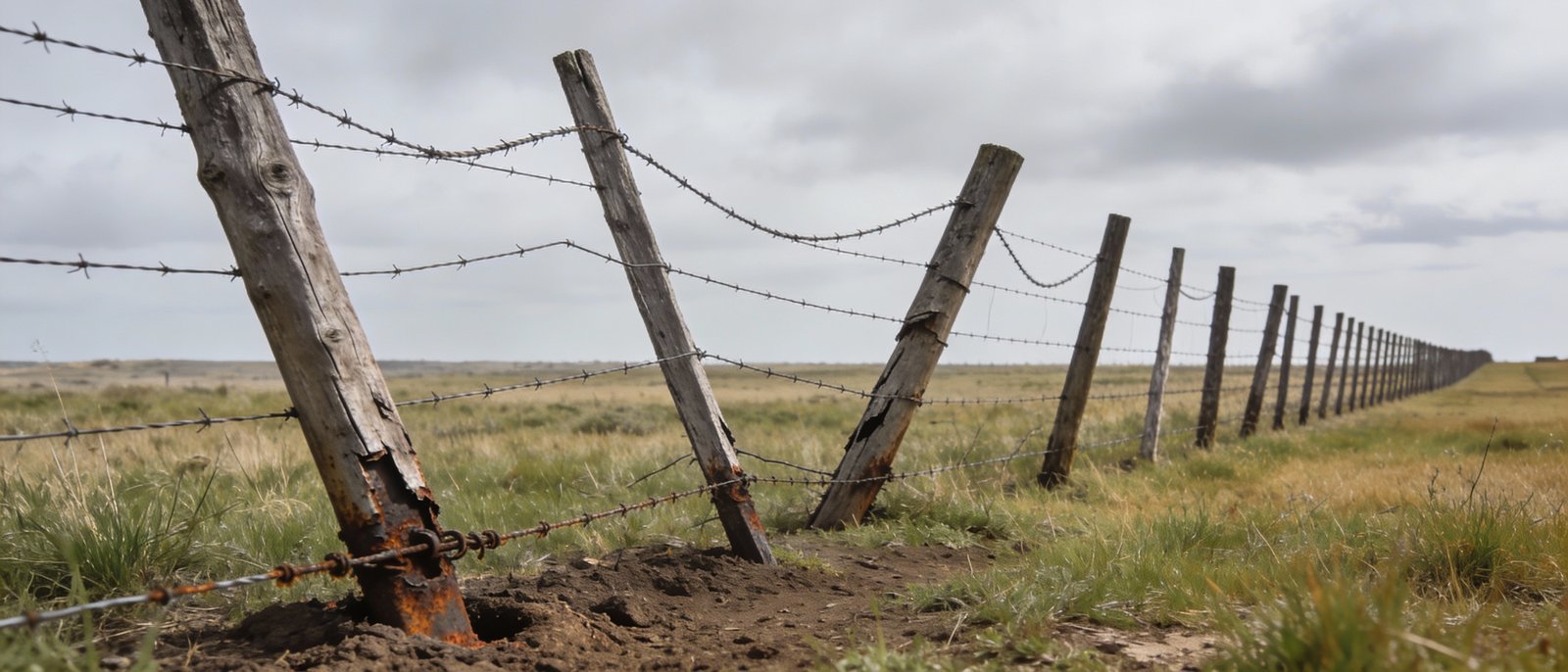
Post Uplift and Stability Issues
Frost heave pushing posts out of ground during freeze-thaw cycles when set above frost line. Most common in regions with seasonal ground freezing where posts experience annual upward movement, accumulating to structural failure within several years.
Wire Tension Loss and Sagging
Low-carbon wire stretching due to inherent elongation characteristics and creep deformation. High-tensile maintains tension far better, requiring re-tensioning every 3-4 years versus annually for low-carbon systems.
Knot Deformation
Cumulative plastic deformation of hinge joint connections under repeated livestock impact. Vertical wires gradually slip from horizontal wires, losing geometric integrity. Fixed knot designs largely eliminate this failure mode through rigid locking mechanism.
Livestock Impact Damage
Bulls testing boundaries during breeding season causing sudden impact loads. High-density grazing creating concentrated pressure on fence sections. Most severe with large-framed breeds weighing over 1,800 lbs.
Environmental Degradation
Salt spray in coastal areas accelerating corrosion rates significantly versus inland. Wind loading causing cyclic fatigue at attachment points. Ice loading during winter storms adding substantial weight to wire spans.
Installation Defects
Inadequate post depth causing premature stability loss. Improper bracing at corners allowing structural shifting. Over-tensioning during installation stressing wires near yield strength. These often manifest within 3-5 years.
Material Degradation
Wood post rot at ground line from fungal decay. Galvanic corrosion at dissimilar metal connections. Wire work-hardening from repeated tensioning cycles. Zinc coating spalling during cold-working at sharp bends.
These failure modes rarely occur in isolation. A fence experiencing ground line corrosion becomes more vulnerable to tension loss and more likely to break during livestock impact. Understanding these interaction effects is critical for comprehensive prevention planning.
The relative frequency varies significantly by environment, livestock type, and installation quality. Coastal operations see corrosion-dominated failures, while northern climates experience more frost heave issues. Bull operations encounter higher rates of impact damage. Professionally installed fences show substantially fewer installation defect failures compared to DIY projects.
At-a-Glance: Why Most Cattle Fences Fail
- Coating class matters more than brand. Class 3 galvanized provides 2-3x lifespan versus Class 1 in most environments—the single highest-impact material specification for corrosion prevention.
- Post depth determines stability. Posts set below frost line (typically 6-12 inches deeper than minimum) eliminate the most common structural failure mode in cold climates.
- Installation quality exceeds material quality in impact. Professionally installed fences experience substantially fewer premature failures—not from better materials, but from adherence to depth, tensioning, and bracing standards.
- Failures compound exponentially, not linearly. Corrosion reduces wire strength, making tension loss more critical; frost heave concentrates stress, accelerating knot deformation. Each mechanism both causes damage and enables other mechanisms.
- High-tensile wire reduces maintenance dramatically. Requiring re-tensioning every 3-4 years versus annually for low-carbon systems—a maintenance reduction that justifies cost premium within first decade.
- Fixed knot doubles livestock fence lifespan. Maintaining structural geometry under repeated impact where hinge joints progressively deform, particularly critical for bull containment and high-pressure applications.
- Prevention costs less than repair. Proper initial installation costs 10-20% more than shortcuts but prevents the majority of common failures. Early intervention extends life substantially at minimal cost versus delayed response requiring major repairs.
Detailed Failure Mode Analysis
Corrosion and Coating Degradation
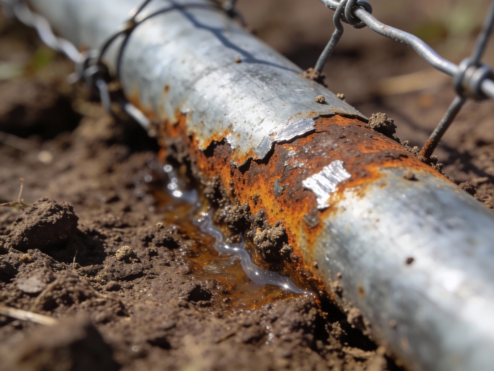
Failure Mechanism
Corrosion represents the electrochemical oxidation of metal in the presence of moisture and oxygen. Galvanized fence wire relies on zinc’s sacrificial protection—zinc corrodes preferentially to steel, forming a protective barrier that slows underlying metal degradation. The corrosion process occurs in stages: atmospheric moisture combines with carbon dioxide forming weakly acidic conditions that begin zinc oxide formation; ongoing exposure consumes zinc coating at rates determined by environmental severity; once zinc depletes significantly, protection becomes non-uniform and steel exposure begins; exposed iron oxidizes far faster than zinc, creating rust that structurally weakens wire.
The corrosion rate varies dramatically by environment. In dry inland areas, zinc corrodes slowly, allowing Class 3 coatings to provide extended protection spanning decades. In humid agricultural regions, rates increase substantially, reducing Class 3 lifespan to the 25-35 year range. In coastal zones with salt spray, corrosion accelerates dramatically, cutting Class 3 protection considerably. Extreme coastal environments can see rates that make Class 1 galvanized functionally inadequate with failure in just a few years.
Ground line corrosion occurs several times faster than above-ground wire due to soil-specific factors: capillary water retention keeping metal continuously moist, microbial activity creating locally acidic conditions, chloride concentration from groundwater salinity, and galvanic effects from dissimilar metals in contact. Clay soils retain more moisture, accelerating ground line attack, while sandy soils with better drainage show slower rates.
Real-World Context
A Texas Gulf Coast ranch documented comparative corrosion across three coating types over 13 years. Class 1 galvanized showed first rust within the initial two years, significant surface coverage by year 3, complete coating failure by year 7, and functional fence collapse requiring replacement at year 10. Class 3 galvanized on the same property showed first rust at year 6, limited surface coverage by year 13, with projected total lifespan in the 20-25 year range. Zinc-aluminum alloy (Galfan) showed first rust after year 10, minimal surface coverage at year 13, with projected lifespan extending well beyond. This substantial lifespan ratio between best and worst coating in identical environment demonstrates coating class’s critical importance in high-corrosion zones.
Midwest agricultural installations with Class 3 galvanized in humid continental climate documented strong 15-year performance with minimal corrosion. The same Class 3 coating in semi-arid Texas showed only surface discoloration after 10 years, with projected lifespan extending significantly due to lower corrosion rates.
ASTM A641 specifies galvanized coating classes by zinc mass per unit area: Class 1 minimum 0.28 oz/ft², Class 3 minimum 0.80 oz/ft². The approximately 3x difference in coating mass translates to substantial difference in service life in most environments. Zinc-aluminum alloys show disproportionate improvement—roughly double the lifespan of Class 3 despite similar coating mass, because aluminum forms a more stable, denser oxide layer that provides superior barrier protection versus zinc oxide.
Prevention and Best Practices
Coating Selection by Environment:
- Coastal zones: Specify zinc-aluminum alloy (Galfan) or minimum Class 3 galvanized. Class 1 will fail prematurely.
- Humid agricultural regions: Specify Class 3 galvanized minimum for permanent fencing. Class 1 acceptable only for temporary applications.
- Semi-arid/arid climates: Class 3 provides extended lifespan; Class 1 can achieve reasonable duration if budget constraints require compromise.
- Industrial zones/highway deicing areas: Specify Galfan or Class 3 with supplemental protective coating due to accelerated chemical attack.
Installation Practices to Minimize Corrosion:
- Install gravel drainage beds at post hole bottoms to prevent standing water and reduce ground line corrosion
- Maintain clearance between bottom wire and soil surface to minimize ground contact corrosion
- Use galvanized or stainless steel fasteners throughout—uncoated steel creates galvanic cells accelerating corrosion
- Avoid concrete collars around metal posts in corrosive environments—concrete retains moisture
- In coastal areas, apply supplemental corrosion-resistant coatings at post/wire connections where abrasion removes factory coating
Maintenance and Monitoring:
- Inspect ground line zones annually for first signs of rust
- Document rust progression with photos—coating failure accelerates exponentially once steel exposure begins
- Apply zinc-rich repair coatings to localized rust spots before penetration reaches steel
- Plan replacement when substantial wire surface shows active rust—structural integrity declining rapidly beyond this threshold
- In high-corrosion environments, implement formal inspection schedule: annual for Class 1, biennial for Class 3, every 3-5 years for Galfan
Economic Justification: 30-year lifecycle cost analysis demonstrates Class 3 and Galfan outperform Class 1 despite higher initial cost. Class 1 requiring multiple installations over 30 years results in substantially higher total cost. Class 3 requiring one installation provides clear net savings. In coastal environments where Class 1 fails early and Class 3 lasts significantly longer, savings exceed $15,000/mile.
Post Uplift and Stability Issues
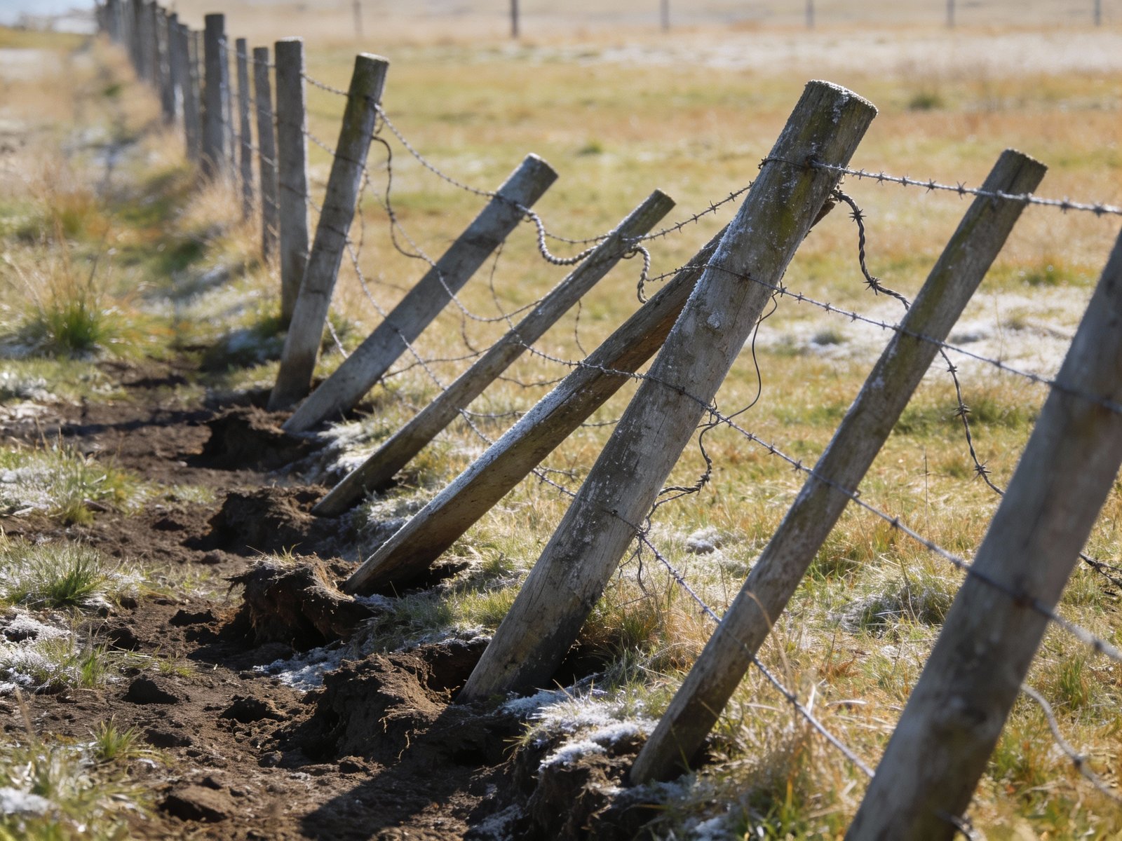
Failure Mechanism
Frost heave occurs through a multi-stage physical process driven by water phase change in soil. When temperatures drop below freezing, soil pore water begins crystallizing into ice. Ice formation creates suction pressure that draws additional water from surrounding soil toward the freezing front—a process called cryogenic suction. This accumulated water freezes into ice lenses—horizontal layers of pure ice that can grow substantially thick. These ice lenses expand volumetrically (water expands approximately 9% when freezing), exerting upward force on any objects intersecting the frozen zone. Posts set within or above the frost-affected zone experience cumulative upward displacement—typically ranging from 1-3 inches per freeze-thaw cycle depending on soil type and moisture content.
The critical engineering parameter is frost line depth—the maximum depth to which soil freezing penetrates during winter. This varies by climate: relatively shallow in southern regions with occasional freezing, moderate depth in temperate zones, and substantial depth in northern climates with extended sub-freezing periods. Posts set above frost line depth act as “fins” conducting cold deeper into soil and providing rigid surfaces for ice lenses to push against. Posts set adequately below frost line anchor in permanently unfrozen soil that resists upward displacement.
Soil type dramatically affects frost heave severity. Fine-grained soils (silts, clays) retain water in micropores and are most susceptible—silt is considered most frost-susceptible soil. Coarse sands and gravels drain freely and show minimal heave. Clay exhibits moderate susceptibility but can create secondary problems: expansive clays swell when wet, exerting lateral pressure on posts even without freezing.
Real-World Context
A Wisconsin dairy operation installed perimeter fencing with corner posts set insufficiently deep in silty loam soil with frost line requiring deeper placement. Within a short period, corner posts showed noticeable heave, fence tension dropped significantly, and gate alignment failed. By year 3, some posts had lifted substantially, requiring complete corner rebuilds. Replacement installation specified proper depth well below frost line with gravel base. After many years with no heave, this demonstrates proper depth specification prevents recurring failure.
Texas Brahman operation installing bull fencing in expansive clay initially set posts at minimum acceptable depth. Within two years, heavy clay shrink-swell cycles caused several posts to tilt noticeably, compromising fence geometry. Post-replacement specification increased depth substantially, anchoring below the active clay expansion zone. Steel pipe posts were substituted for wood in corner positions due to superior dimensional stability under soil movement. This installation showed zero movement over subsequent years.
Soil freezing physics follows predictable relationships that relate frost penetration depth to cumulative freezing degree-days, soil thermal properties, and moisture content. This allows frost line mapping—USDA publishes frost depth maps showing maximum depths by county, which building codes reference for foundation specifications. Lateral bearing capacity of posts depends on soil-post friction and passive earth pressure on embedded length. Doubling embedment depth increases lateral resistance approximately fourfold due to squared relationship between depth and overturning moment arm.
Prevention and Best Practices
Frost Heave Prevention:
- Determine local frost line depth from building codes, NRCS technical guides, or university extension
- Set all posts minimum 6 inches below frost line; deeper provides safety factor for unusual winters
- For maximum-risk scenarios (silty soils + high water table + severe climate), use deeper standards
- Install gravel drainage layer at bottom of all post holes—uses free-draining material that won’t heave and prevents water accumulation
- In extremely frost-susceptible soils, consider replacing native soil around posts with free-draining gravel/sand column extending full depth
Expansive Clay Mitigation:
- Set posts deeper to penetrate below active shrink-swell zone
- Use rigid post materials (steel pipe, large-diameter treated posts) that resist lateral deflection
- Install gravel collars around post perimeter to buffer lateral pressure
- Compact backfill in lifts to maximize soil-post friction
General Post Stability Guidelines:
- Minimum depth rule: one-third of total post length; corners/gates/high-stress points use half length
- Top wire rule: Post depth should equal or exceed top wire height for overturning resistance
- Corner/brace posts: Always deeper than line posts—substantial minimum regardless of soil
- Tamping critical: Bottom portion most important—compact thoroughly in lifts, not all at once
Wire Tension Loss and Sagging
Failure Mechanism
Wire tension loss occurs through multiple physical processes, each with distinct timescales and magnitudes. Creep deformation represents permanent elongation under continuous load below yield strength. Low-carbon wire exhibits substantial elongation at failure, with continuous creep over time even at working loads. High-tensile wire shows minimal elongation with minimal creep, representing a dramatic improvement in dimensional stability.
Thermal expansion and contraction follows the coefficient of thermal expansion for steel. For typical fence spans, moderate temperature changes cause measurable length changes, equivalent to significant tension variations in high-tensile wire. The relationship is approximately linear: modest temperature changes equal proportional tension changes per wire. Climates with large annual temperature ranges can see substantial tension swings if wire is rigidly constrained.
Stress relaxation represents molecular-level rearrangement in metal under sustained load. Even high-tensile wire loses a portion of initial tension over the first couple years as internal stresses equilibrate. This is distinct from creep and is unavoidable in any tensioned system. Proper design accounts for this by setting initial tension appropriately, providing buffer as relaxation occurs.
Real-World Context
A Midwest cattle operation installed high-tensile perimeter fence with appropriate initial tension, set in moderate temperatures. First winter saw substantial temperature drops. Ranch manager noted fence was very tight but no failures occurred. Spring inspection revealed tension had decreased as expected as temperatures moderated, representing normal relaxation from stress relief. By year 3, tension had stabilized, requiring re-tensioning to restore optimal geometry. Total maintenance over 15 years: two re-tensioning events of modest duration each.
Comparative example using low-carbon wire: Adjacent property installed traditional low-carbon wire at similar initial tension. Within months, visible sagging appeared at mid-spans. Ranch manager re-tensioned, but within another year, sagging recurred. By year 5, fence required complete re-tensioning annually to maintain adequate geometry, totaling substantially more maintenance over same period—nearly four times the high-tensile maintenance requirement.
Material testing per ASTM A116 (woven wire fence fabric) and ASTM A121 (barbed wire) establishes minimum tensile strength and elongation properties. Class 1 and Class 3 refer to coating, not tensile properties—both are available in low-carbon and high-tensile grades. The critical specification is tensile strength. Engineering stress-strain curves show fundamental difference: low-carbon wire has long plastic region (yields at low stress, continues deforming to failure), while high-tensile wire has minimal plastic region (elastic up to near-breaking load, then sudden failure). This explains performance difference—low-carbon continuously deforms under working loads, while high-tensile remains elastic.
Prevention and Best Practices
Wire Type Selection:
- Permanent fencing (target lifespan exceeding 15 years): Specify high-tensile wire exclusively—substantially longer maintenance intervals justify modest cost premium
- Temporary fencing (under 5 years): Low-carbon acceptable if budget constrained, but plan annual re-tensioning
- High-temperature environments (annual range exceeding 80°F): High-tensile mandatory to handle thermal cycling without fatigue failure
- Low-maintenance applications (remote, difficult access): High-tensile with inline spring tensioners to minimize maintenance requirements
Initial Tensioning Guidelines:
- Use recommended tension ranges for wire gauge and type
- Temperature compensation: Set tension at mid-range annual temperature (typically 60-70°F in spring or fall)
- Avoid tensioning in temperature extremes—wait for moderate conditions
- Never exceed safe working load limits during tensioning
Maintenance Schedule:
- High-tensile fences: Years 1-2 inspect semi-annually, expect modest loss from stress relaxation; Years 3-5 re-tension as needed, typically once during this window; Years 5+ inspect annually, re-tension every few years
- Low-carbon fences: Annual re-tensioning typical
- All fences: Document initial tension and installation temperature for future reference
Knot Deformation and Structural Weakness
Failure Mechanism
Knot deformation represents progressive geometric failure where connections between vertical and horizontal wires lose their designed spacing and load distribution. Hinge joint knots consist of vertical wires wrapped around horizontal stay wires, creating a flexible connection. Under load, hinge joints function as designed—they flex and absorb energy. However, repeated livestock impact causes cumulative plastic deformation through micro-bending at the wire wrap. Each cycle—cattle leaning, rubbing, or pushing—creates small permanent angular changes. After hundreds or thousands of loading cycles, these accumulate into visible deformation: vertical wires migrate downward or laterally, mesh geometry becomes irregular, and wire spacing increases.
The deformation timeline follows predictable stages: Years 1-3 show minimal visible change; Years 4-7 show visible sagging in high-traffic zones with vertical wire angles shifting noticeably; Years 8-12 show widespread geometric irregularity with some vertical wires nearly parallel to horizontal; Years 12-15 show extensive knot opening with vertical wires partially or fully unwrapped, requiring repair or replacement.
Fixed knot designs use a separate third wire that wraps around both horizontal and vertical wires under mechanical pressure, creating a rigid triangulated connection. This geometry prevents relative movement between wires—the knot cannot flex without breaking the locking wire. Under the same livestock loading that causes hinge joint deformation, fixed knots either maintain geometry completely (if load is within design limits) or fail catastrophically through wire breakage (if load exceeds limits). There is no intermediate progressive degradation. Field data shows fixed knot fences maintain the vast majority of original geometry after many decades under moderate-to-high livestock pressure, versus hinge joints showing substantial geometry loss over their shorter lifespan under identical conditions.
Real-World Context
A comparative Texas ranch study documented hinge joint and fixed knot performance on adjacent properties with identical livestock (mixed cow-calf operation, rotational grazing). Both fences installed same year, identical Class 3 galvanized coating, similar post spacing appropriate for each design. Hinge joint showed progressive deterioration: Year 5 first visible sagging near gates and water troughs; Year 8 vertical wire migration visible across significant fence length; Year 11 localized repairs required where mesh height had decreased substantially; Year 14 major maintenance event with extensive section replacement; Year 17 planning complete replacement. Fixed knot timeline showed dramatically different pattern: Year 5 no visible changes; Year 10 minimal wear at rubbing posts with knots maintaining geometry; Year 15 routine inspection showed minimal knot deformation within normal tolerance; Year 17 projected extended lifespan before replacement needed. Cumulative maintenance differential and material costs favor fixed knot despite higher initial investment.
University extension field trials compared knot types under controlled bull pressure. After 3 years, hinge joint fence showed measurable vertical wire displacement, while fixed knot fence maintained geometry with minimal displacement. Australian transport industry testing evaluated fence systems under vehicle impact simulation. Hinge joint fences experienced catastrophic mesh collapse with vertical wires completely separated. Fixed knot fences experienced localized wire breakage but maintained overall geometry—fence remained functional barrier even post-impact, demonstrating fundamental structural superiority under extreme loading.
Prevention and Best Practices
Knot Type Selection by Application:
Fixed Knot Mandatory For:
- Bull containment or breeding operations
- High-density grazing systems
- Perimeter fencing for high-value operations
- Any application with target lifespan exceeding 20 years
- Boundary fences where failure creates liability risk
- Areas with aggressive livestock behavior
Hinge Joint Acceptable For:
- Temporary fencing (under 10 year expected use)
- Internal subdivisions with low livestock pressure
- Applications where terrain conformability critical
- Budget-constrained projects where shorter lifespan acceptable
- When paired with electric offset wire to reduce physical fence contact
Installation Practices to Maximize Knot Longevity:
- Maintain proper tension during installation—under-tensioning allows excessive wire movement accelerating knot wear
- Ensure adequate post spacing for design: hinge joint closer spacing, fixed knot standard spacing, reduce for high-pressure applications
- Install rubbing posts or trees adjacent to fence in areas where cattle naturally congregate—diverts contact away from wire
- Use corner bracing adequate for fence tension—inadequate bracing allows geometry shift stressing knots unevenly
Monitoring and Maintenance:
- Annual inspection focus areas: gates and corners, feeding stations and water sources, rubbing posts and shade areas
- Deformation indicators: vertical wires no longer perpendicular, visible increase in mesh spacing, sagging at mid-span, knots showing visible opening
- Intervention thresholds: localized deformation repair with splice or panel replacement; moderate deformation re-tension and monitor; extensive deformation replacement more cost-effective than repair
Cross-Mode Interactions and Compounding Effects
Fence failures rarely result from single isolated mechanisms. Instead, multiple degradation processes interact synergistically, accelerating overall system decline. Understanding these interaction effects enables more effective prevention strategies that address root causes rather than treating symptoms.
Corrosion-Tension Interaction
Wire corrosion reduces effective cross-sectional area, which increases stress (force per unit area) for any given tension load. When corrosion reduces effective diameter moderately, cross-sectional area decreases disproportionately. For a given tension, stress increases proportionally. This moves wire closer to yield strength, reducing safety margin. Additionally, corrosion creates stress concentration sites—pits and surface irregularities where local stress can be several times average stress. Under thermal cycling or livestock impact, these become crack initiation points leading to sudden wire failure at loads well below nominal breaking strength.
Frost Heave-Tension Interaction
Frost heave lifting posts creates geometry changes that stress wire systems. As posts rise, wire between posts must accommodate additional length. For fixed-end constraints (wire securely attached at corners/gates), this forces wire to either stretch elastically (high-tensile can accommodate small changes) or deform plastically (low-carbon stretches permanently). More critically, post heave creates uneven loading. Posts that heave differentially create “sawtooth” geometry. Wires attached to high posts carry disproportionate tension, while wires at low posts go slack. This uneven distribution concentrates stress at high posts, accelerating staple pullout and wire breakage at those locations.
Corrosion-Frost Heave Interaction
Ground line corrosion and frost heave create particularly destructive synergy. Ice lens formation concentrates at ground line where temperature gradient is steepest. Corroded wire at this location has reduced cross-section and degraded surface condition—both increasing susceptibility to frost damage. Field observations show ground line wire failures occur significantly earlier in frost-susceptible soils versus well-drained soils, even with identical coating class. This isn’t simply additive effect but multiplicative—heaving accelerates corrosion by repeatedly breaking protective oxide layers, while corrosion weakens wire making it more vulnerable to mechanical stress from heaving.
Knot Deformation-Livestock Pressure Interaction
Hinge joint deformation and livestock behavior create reinforcing cycle. Initial deformation (vertical wires beginning to angle) creates visual and tactile cues that cattle interpret as fence weakness. This encourages testing behavior—pushing, leaning, rubbing—which accelerates deformation. As deformation progresses, fence deflection under pressure increases (reduced geometric stiffness), providing positive feedback to livestock that pressure works. Research on animal behavior shows cattle learn boundary rules primarily through early experiences. A fence that yields substantially when pushed teaches “push harder works,” even if fence ultimately contains the animal.
Practical Implications for Fence Design
- Address highest-severity risk first: In coastal environments, coating class matters more than wire gauge. In frost-susceptible areas, post depth matters more than tension settings. Identify primary stressor for your environment and over-specify that parameter.
- Provide redundancy at critical points: Corner assemblies, gates, and high-traffic areas should use specifications beyond minimum standards—these locations experience compound loading from multiple failure mechanisms simultaneously.
- Avoid marginal specifications: Interaction effects mean fence specified to “barely meet” requirements in any dimension will fail prematurely. The modest cost increase from Class 1 to Class 3 coating provides substantial lifespan improvement not because coating is proportionally better, but because it provides margin against compound stresses.
- Prioritize installation quality: Poor installation creates multiple failure mechanisms simultaneously. Posts set too shallow enable both stability issues and tension problems. Improper tensioning accelerates both wire deformation and fastener failures.
- Maintenance timing critical: Early intervention breaks compounding cycles. Re-tensioning fence showing minor sagging prevents knot deformation from progressing to require replacement. Treating ground line rust prevents corrosion from reaching steel where deterioration accelerates dramatically.
This systems-level understanding connects directly to environment-specific fence selection guidance and explains why case studies show such dramatic performance differences between seemingly similar installations—small specification or installation differences create large outcome divergences when interaction effects operate over years.
Prevention Framework and Decision Summary
Effective fence failure prevention requires systematic approach addressing material selection, installation quality, environmental adaptation, and maintenance planning. This framework synthesizes failure mode analysis into actionable decision rules.
Material Selection Decision Tree
| Decision Factor | Condition | Specification |
|---|---|---|
| Environmental Corrosivity | Coastal, industrial, deicing areas | Zinc-aluminum alloy (Galfan) or minimum Class 3 galvanized |
| Environmental Corrosivity | Humid agricultural (30+ inches precipitation) | Class 3 galvanized minimum |
| Environmental Corrosivity | Semi-arid to arid (under 20 inches precipitation) | Class 3 preferred; Class 1 acceptable for temporary |
| Target Lifespan | Over 20 years | Class 3 minimum; Galfan in high-corrosivity |
| Target Lifespan | 10-20 years | Class 3 for moderate-to-high corrosivity |
| Target Lifespan | Under 10 years | Class 1 acceptable if budget constrained |
| Wire Properties | Permanent, low-maintenance | High-tensile wire mandatory |
| Wire Properties | Extreme temperature climates (over 80°F range) | High-tensile mandatory for thermal cycling |
| Knot Design | Bulls, high-pressure, lifespan over 20 years | Fixed knot mandatory |
| Knot Design | Standard livestock, moderate pressure | Fixed knot strongly preferred |
Installation Quality Checklist
Post Depth and Stability
- Determine local frost line depth (building codes, NRCS, university extension)
- Set all posts minimum 6-12 inches below frost line
- Use minimum one-third total post length embedment; half length for corners/gates/high-stress
- Adjust for soil type: sand requires half length, expansive clay requires depth below active zone
- Install 6-8 inch gravel drainage bed at bottom of all post holes
- Compact backfill in lifts, not all at once
Corner and Brace Assembly
- Use H-braces or diagonal braces at all corners and direction changes exceeding 20 degrees
- Set corner posts minimum 4-5 feet deep regardless of line post requirements
- Use minimum 8-inch diameter corner posts (wood) or 6-inch steel pipe
- Install brace posts at substantial depth relative to corner posts
- Space brace assemblies appropriately on straight runs
- Verify brace compression member properly seated and secured
Wire Tensioning
- Tension at moderate temperature (60-70°F) to center seasonal range
- Use calibrated tension meter or load gauge—do not estimate by feel
- Follow recommended tension ranges for wire gauge and type
- Never exceed safe working load limits during tensioning
- Check tension uniformity across all wires—variation exceeding 20% indicates improper technique
- Document initial tension and installation temperature for future reference
Environment-Specific Adaptations
Coastal Environments: Galfan or Class 3 minimum coating, galvanized steel posts preferred, stainless steel fasteners mandatory, critical drainage around all posts, annual inspection for ground line corrosion.
Frost-Susceptible Regions: Post depth 42-48 inches minimum, mandatory gravel beds at all post holes, high-tensile wire to accommodate thermal cycling, post-winter annual check for heave.
High-Temperature Arid Climates: Class 3 provides extended lifespan, reduce initial tension to account for high summer temperatures, UV-stabilized components for electric fence elements, minimal corrosion but monitor tension more frequently.
Bull and High-Pressure Applications: Heavier gauge fixed knot with Class 3 coating minimum, reduced post spacing, deeper post depth, higher tension carefully monitored, supplemental electric offset wire as psychological deterrent, quarterly inspection in year 1.
Maintenance Planning
High-Tensile Fixed Knot Fences:
- Years 2-5: Annual walk-through inspection, re-tension once as stress relaxation stabilizes
- Years 5-15: Biennial inspection, re-tension every 3-4 years or as needed
- Years 15-25: Annual inspection focusing on ground line corrosion, re-tension every 3-4 years
- Years 25+: Planning for selective section replacement or full rebuild depending on coating condition
Low-Carbon or Hinge Joint Fences:
- Annual re-tensioning typical
- Biannual inspection of high-traffic areas for knot deformation (hinge joint)
- Years 8-12: Plan for major maintenance (partial replacement) or full rebuild
All Fences:
- Post-winter inspection for frost heave in susceptible areas
- Mid-summer inspection for excessive sagging indicating tension loss
- Quarterly inspection of gates and high-traffic areas
- Immediate inspection following extreme weather events
Decision Summary: Prevention Investment Prioritization
When budget constraints require trade-offs, prioritize investments with highest failure prevention impact:
Tier 1—Highest Impact (prevent multiple failure modes):
- Adequate post depth: Prevents frost heave, improves stability, extends fence life substantially
- Class 3 coating in moderate-to-high corrosivity: Prevents corrosion failure, doubles lifespan versus Class 1
- High-tensile wire: Prevents tension loss, reduces maintenance dramatically
Tier 2—High Impact (prevent specific high-frequency failures):
- Fixed knot design: Prevents knot deformation, doubles lifespan in livestock applications
- Proper corner bracing: Prevents corner failure cascade, protects entire fence system investment
- Gravel drainage: Prevents frost heave and corrosion, extends post life
This prioritization enables rational decision-making when budget limits prevent implementing all best practices. Rancher with limited budget should invest in Class 3 coating, adequate post depth, and high-tensile wire before considering advanced upgrades—those first three interventions prevent the majority of common failures for reasonable cost increase over bare-minimum specifications. See our detailed installation guide for step-by-step procedures implementing these standards.
Frequently Asked Questions
Why do fences corrode faster in coastal areas?
Coastal corrosion acceleration results from three synergistic factors. First, salt spray deposits chloride ions on metal surfaces. Chlorides are extremely aggressive to zinc and steel, accelerating electrochemical oxidation several times versus chloride-free environments. Second, high humidity means metal surfaces remain wet much longer after rain events—corrosion occurs only in presence of moisture, so extended wet periods dramatically increase cumulative corrosion time. Third, salt is hygroscopic (attracts and retains water), meaning surfaces with deposited salt remain wet even during periods without active precipitation. Combined, these create nearly-continuous corrosive conditions versus inland areas where surfaces dry between rain events. This explains why Class 1 wire lasting a decade or more inland fails within several years coastal, and why Galfan specification is justified despite substantial cost premium.
How much post depth is required to prevent frost heave?
Minimum post depth to prevent frost heave equals local frost line depth plus 6-12 inches. Frost line represents maximum depth of soil freezing during winter and varies by climate: relatively shallow in southern regions with occasional freezing, moderate in temperate zones, substantial in northern climates and high elevations. Local building codes, NRCS technical guides, and university extension services publish frost line maps by county. Setting posts 6-12 inches below frost line ensures post base anchors in permanently unfrozen soil that cannot heave. Additionally, install 6-8 inch gravel drainage bed at post hole bottom—free-draining gravel cannot heave and prevents water accumulation that drives ice lens formation. Cost of adequate depth: modest additional per post. Cost of frost heave repair: substantially higher per post plus labor for removal/reinstallation.
Can high-tensile wire prevent sagging?
High-tensile wire dramatically reduces but does not completely eliminate sagging. The fundamental difference is elongation characteristics: low-carbon wire exhibits substantial elongation at failure with continuous creep under working loads, while high-tensile wire shows minimal elongation with minimal creep. This dramatic improvement means high-tensile wire maintains tension far better over time. Field data documents modest tension loss over 15 years for properly installed high-tensile fence versus substantial loss requiring annual re-tensioning for low-carbon. However, high-tensile does not prevent all sagging because thermal expansion/contraction still occurs, causing temporary sagging during hot weather, and stress relaxation causes some tension loss in first couple years. Net result: high-tensile fences typically require re-tensioning every 3-4 years versus annually for low-carbon—a substantial reduction in maintenance frequency. For optimal performance, combine high-tensile wire with proper initial tensioning, inline spring tensioners to absorb thermal cycling, and adequate post spacing. See our maintenance and repair guide for detailed procedures.
What causes knots to fail on hinge joint fences?
Hinge joint knot failure occurs through cumulative plastic deformation under repeated livestock impact loading. The mechanism: hinge joints consist of vertical wires wrapped around horizontal stay wires, creating flexible connection that allows fence to conform to terrain. Under load, this connection flexes—exactly as designed. However, each flex cycle causes microscopic bending and work-hardening at the wire wrap. After hundreds or thousands of loading events (cattle leaning, rubbing, pushing), these micro-deformations accumulate into visible geometric changes: vertical wires migrate downward or laterally, wire spacing increases, mesh height decreases. The knot doesn’t “break” suddenly; it progressively loses structural function over years. Fixed knot designs prevent this failure mode through rigid three-point constraint—separate third wire locks both horizontal and vertical wires, preventing relative movement. Under identical livestock pressure, fixed knots maintain the vast majority of original geometry after many decades versus hinge joints showing substantial geometry loss within their shorter operational lifespan.
Does wire gauge matter more than coating class?
For most applications, coating class has greater impact on fence lifespan than wire gauge. Wire gauge affects breaking strength and thus safety margin against overload, but coating class directly determines corrosion resistance and time-to-failure in most environments. Quantitative comparison: upgrading wire gauge increases breaking strength substantially, providing greater safety margin but not preventing failure mechanisms. Upgrading from Class 1 to Class 3 coating increases zinc mass approximately three times, extending time-to-corrosion-failure from several years to several decades depending on environment—a dramatic lifespan improvement. Economic analysis: gauge upgrade costs modest premium, coating upgrade costs similar premium—comparable percentage increase but coating delivers larger longevity benefit. Exception cases where gauge matters more: bull containment or high-impact applications where breaking strength is primary concern and corrosion is secondary; planned short-term use where fence will be replaced before corrosion becomes significant. Recommended prioritization for permanent fencing: coating class appropriate for environment first, high-tensile versus low-carbon tensile properties second, wire gauge for safety margin third.
What maintenance can extend fence life most cost-effectively?
Three maintenance interventions provide highest return on investment. First, ground line corrosion treatment when rust first appears. At this early stage, zinc coating is consumed but steel not yet exposed—applying zinc-rich repair paint re-establishes sacrificial protection, preventing progression to accelerated steel corrosion. Benefit: extends fence life substantially by preventing steel exposure that would otherwise cause failure within a few years. Second, timely re-tensioning when sagging first becomes visible. Early intervention requires only modest tension adjustment, while delayed re-tensioning after severe sagging requires large tension increases stressing posts and hardware. Benefit: prevents knot deformation in hinge joint systems, reduces livestock testing behavior, extends fence function significantly before next maintenance cycle needed. Third, post rot inspection and selective replacement before catastrophic failure. Annually inspect ground line of wood posts for soft spots (indicates fungal decay), particularly after wet seasons. Replace individual posts showing early decay prevents progressive failure where compromised post allows fence geometry shift stressing adjacent posts. Lower-priority maintenance: staple re-attachment, vegetation control. Maintenance to avoid: over-tensioning attempting to compensate for other degradation—stresses all components, often causes more failures than it prevents.
Summary: From Failure Analysis to Prevention Strategy
Cattle fence failures follow predictable patterns driven by material properties, environmental stressors, installation quality, and livestock behavior. While individual failure modes can be analyzed separately, real-world fence degradation typically involves multiple interacting mechanisms that compound over time.
The evidence from field performance data, engineering standards, and practitioner experience converges on several fundamental principles:
Material specifications matter more than brand names. Coating class determines time-to-corrosion-failure, with substantial lifespan differences across classes. Tensile properties determine maintenance intensity, with dramatic differences in re-tensioning frequency. Knot design determines geometric stability under livestock pressure, with substantial lifespan differences. These specification choices create performance divergences far exceeding any brand-to-brand variations within specification classes.
Installation quality often exceeds material quality in impact on longevity. Posts set at inadequate depth fail regardless of coating class. Improperly tensioned wire develops problems regardless of tensile properties. Inadequate corner bracing compromises entire fence system regardless of individual component quality. Field data shows professionally installed fences experiencing substantially fewer premature failures than DIY installations—learn more about this trade-off in our DIY versus professional installation analysis.
Environment requires adaptive specification. Identical fence materials perform dramatically differently across environments: Class 3 galvanized provides extended lifespan in arid climates, moderate lifespan in humid agricultural regions, reduced lifespan in coastal zones. Frost line depth varies substantially from south to north, requiring proportional post depth adjustments. One-size-fits-all specifications ignore these environmental realities and result in either over-spending or premature failure.
Lifecycle cost analysis favors quality specifications. Class 3 coating costs moderately more than Class 1 but provides substantially longer lifespan—dramatically lower cost per year of service. High-tensile wire costs modestly more than low-carbon but reduces maintenance labor dramatically. Fixed knot costs moderately more than hinge joint but doubles lifespan in livestock applications. These quality premiums pay back within reasonable timeframes through avoided replacement costs and reduced maintenance labor.
For ranchers and farm managers evaluating fence investments, the key actionable insight is straightforward: invest in failure prevention, not failure recovery. The specification and installation decisions made during fence construction largely determine whether the fence serves reliably for decades or requires major repairs or replacement within a much shorter timeframe. Making those decisions based on understanding of failure mechanisms, rather than on immediate cost minimization, represents the practical application of this failure analysis framework.